Advertisement

Showing posts with label Pet Food Dispenser. Show all posts

Saturday, April 19, 2014

Tested Motor PCB With RPi and Motor

Earlier this week, we assembled the Raspberry Pi Motor Controller Board (aka RTK RPi MCB) from Ryanteck, Ltd.  Today, I spent a few hours experimenting with controlling motors using the RPi and the RTK MCB.

RTK RPi MCB Basics
The documentation that is provided with the RTK MCB is pretty sparse.  Here are some things that I learned while putzing that I wish was in the documentation.

First, there are two ways that the RTK MCB can be attached to the RPi's pins.  When attached properly to the RPi, the board will mainly hang over the RPi.  See the picture to the right.  If the MCB is attached the wrong way, it will hang over the table.

Second, as the documentation says, the left-hand input on the J1 VCC2 terminal block is for positive power.  The right-hand input is for ground.  The positive input is on the left when you face the terminal block to insert the wires.

Next, the J2 and J3 terminal blocks are to connect to the motors. J3 is for motor one.  J2 is for motor two.  The circuit that connects to the terminal blocks works as follows:

  • GPIO 17 / Pin 11 on the RPi connects to the left-hand input on terminal block J3 
  • GPIO 18 / Pin 12 on the RPi connects to the right-hand input on terminal block J3
  • GPIO 22 / Pin 15 on the RPI connects to the right-hand input on terminal block J2
  • GPIO 23 / Pin 16 on the RPI connects to the left-hand input on terminal block J2
This is a bit confusing.  Say your motor has a red and a black wire.  If you plug the red wire into the left input on terminal J3 and send power out GPIO 17, it will spin the motor in one direction, for example clockwise.  Then, you plug the red wire into the left input on terminal J2 and send power out GPIO 22, it will spin the motor counter-clockwise.  It would make more sense if applying power to GPIOs 17 and 22 made the same motor spin the same way.

In order to power a motor, you have to set one of the pins HIGH and the other pin LOW on a terminal block.  Setting one pin HIGH but not setting the other pin will not work.

Finally, I have no idea what pin headers J4, J5, and J6 are for.  The are labeled 3V3, GND, and I2C respectively.  The documentation does not explain their purpose and they are not needed to run the motors.  It would be nice to have a circuit diagram for the PCB.

Power Supplies
The manual for the MCB says that the board will accept 4.5v to 12v power supplies to power the motor.  I first connected a 9v battery to the MCB.  However, the actual output power was about 4.5 volts.  Not sure why the board does not pass more power through to the motor.

I connected a 12v, 200mA power supply and it worked much better.  More on that below.

Trying to run two motors at the same time seems to make each motor run slower than just powering one motor.  Maybe a PSU that put out more amps would help in this case.

Python Code
I spent a lot of time working on python code to drive the motors.  I had a program from a website that had a circuit driving a motor through a transistor.  I used it as a base and modified it to have the following features:

  • accept inputs for the motor to power (1, 2, or both), the time the motors will run, and the amount of power to send to the motors
  • power one or both of the motors for whatever length of time the user specifies
  • spin the motor first clockwise for one second.  Then, counterclockwise for 1.5 seconds.  Repeat for the allotted time.
  • control how fast the motors spin using pulse width modulation.
Here is a link to the program I used to control the motor.

Testing with the Auger
Now that the MCB is assembled and the python program works, we did some testing with the auger.  The first test was to try to push food through a 2" tube.  The 9v battery was the power source.  Unfortunately, it would not push much food through the tube.  Sometimes, it would not spin at all.

We tried using a smaller, 1" tube.  The motor would not spin the auger at all with food in the tube.  We changed the program so it spun the motor clockwise for 5 seconds instead of 1 second.  That did nothing.

Next, we connected a 12v, 200mA power supply as the motor power source.  The motor had no problem pushing food through the 2" tube with this much power.  We played with the time and power settings.  It looks like the best settings are to run the motor for 10 seconds at 75% power.  This will push the right amount of food into the bowl.

One problem is that the screw that is supposed to keep the motor's shaft in the connector is not tight enough to hold the shaft.  A piece of the allen wrench used to tighten the screw broke off in the screw.  Now, it cannot be removed.  I'm not sure how I will remove it but it needs to be fixed to continue experimenting .

It would also be nice to have something to hold the motor down while testing.  I'll have to build something.

Wednesday, April 16, 2014

Assembled Raspberry Pi Motor Controller Board Kit

Tim and I are building an automated pet feeder.  One thing we need to do is control a motor with the Raspberry Pi.  There are several ways to do this but I chose to use a controller board that was made to control motors.  I ordered the Raspberry Pi Motor Controller Board Kit from Adafruit.  The kit is made by Ryantech Ltd. and costs about $20 plus shipping.  That's a bit more than I was hoping to spend but I'm pretty sure it will do exactly what I need.  Plus, Tim and I can put it together ourselves.


The board can control up to two motors at once (we are only going to control one motor).  We have a 12v power supply that will connect to the board and provide power to the motor.  The board will let the Pi turn the motor in both directions.

I had Tim do the actual soldering work.  He had it done in about thirty minutes and did a great job.  We applied solder flux to the holes on the PCB to make the soldering a bit easier.  Then, we followed the instructions to solder each part to the PCB.  It really was quite easy.

One other hint related to soldering is to place the component upside down on the work surface and put the board on top of the component.  Gravity will keep the work on the component.  We had to add something under the other end of the PCB to support it.

We did not test the PCB with the Raspberry Pi.  That will come next.


Tags: #raspberrypi #petfeeder

Friday, April 4, 2014

Ordered a Motor Control Board for Raspberry Pi

Tonight, I wanted to make some progress on the automated pet food dispenser project.  One of the next things to figure out is how to control the motor using my Raspberry Pi microcontroller.  I did some research.  There are various options.  For example, there are chips like the L293D stepper motor driver or the L293E.  We did not have those drivers at the Makerspace.

There are also several different boards that will drive motors.  I decided to go with the RTK Motor Controller Board Kit from Adafruit.  It's a kit that I can solder together with my son as a mini-project.  Plus, it's relatively inexpensive and it will control a motor from my Pi.  I am sure there are a dozen other ways to control a motor from my Raspberry Pi but this is a good option for me.

Right after I ordered the board from Adafruit, Vishal, another member at the Milwaukee Makerspace talked to me about making my own circuit.  I did find a circuit on the internet that uses an NPN transistor to enable the circuit.  I wired up the circuit on a breadboard and hooked up a 12v power supply.  The motor turned on.  That was strange because I did not have it hooked up to the pi. 

I'll have to do more research.


Tags: #Motor, #RaspberryPi

Thursday, March 27, 2014

Testing Motors and Pipes for Automated Pet Feeder

Tim and I worked on the automated pet feeder yesternight.  We tested the motor to see if it could push dog food through the pipe.  In all the tests, we used the 8" long, 1" diameter auger that I bought at the hardware store and a 17 volt DC motor that I found on the hack rack at the Milwaukee Makerspace.

Small Pipe
We started out using a pipe with a 1.5" inside diameter.  First, we hooked up a 5v power supply to the motor.  It did not have enough power to push the food through the tube.  Pieces would get stuck on the lip of the hole.  We tried reversing the power so the auger went backwards, then had it turn forward.  This did not help.

Next, we hooked up a 9v power supply.  Pieces still got stuck on the lip.  The motor could not push the pieces through.

Big Pipe
For the next test we used a T shaped pipe with a 2" inside diameter.  This was the pipe and wood stand that we were going to use for the other pet feeder project.  The 5v power supply did a bit better in this pipe, but the food still got stuck.  The motor was not able to push it through.

The 9v power supply faired much better.  It was able to push the food through most of the time but it still got stuck.  Again, we reversed the spin on the motor and it seemed to work better.  One downside to using a 9v power supply with this motor is that it spins so fast it will fill up the bowl in about five seconds.

Solution Ideas
We think the final solution should use the 2" ID T PVC with the 9v power supply.  In order to make sure the food is always pushed through the pipe, a raspberry pi will be used to spin the auger forwards and backwards.  The RPi will also control how long the motor operates.

One other problem is getting the RPi to control the power flow from the 9v PSU.  The current idea is to use a DC to DC relay.  The 9v PSU will plug in to the relay.  The RPi would turn the relay on and off allowing the PSU to power the motor.

The next step is to test the RPi with a relay and a motor.  A python program is needed to make the motor spin both directions for a specific amount of time.


#petfeeder

Sunday, March 23, 2014

Automated Pet Food Dispenser -- 2

Tim and I started working on a different version of the automated pet food dispenser.  Originally, I was trying to duplicate a design I saw on Instructables.  Long-story-short, I could not get the 3D printed pieces to mate with the PVC T.  I tried grinding off some surface area of the various pieces but they just got ruined.

So, we switched gears and are going to make a more traditional project based on something I saw on YouTube.  This is actually better because Tim and I can work on it together.  The former project was something I was mostly doing alone at the Milwaukee Makerspace.  We can work on this project together at home.

Motor
The first step was to get a new motor.  I found a small 17 volt DC motor on the hack rack at the Makerspace. It seems to be a good choice for this project. I wanted a motor that would not spin too fast but also had enough torque to push the food through if it got stuck.  I can get both torque and slow speed by putting only 5 or 7 volts DC into the motor.

Power
I'm not exactly sure how we will power the motor. One idea would be to use a common AC to DC power supply. I  have one that provides 5v and one that provides 12v. The 5v PSU spins the auger at the right speed.  Not sure if it has enough torque. The PSU would plug in to a timer that would turn it on for a enough time to fill the bowl once a day or so.

The other idea is to connect the motor to an Arduino or Raspberry Pi. The advantage of this is that the device can provide power for a specific time on a specific schedule. It could change the direction of the motor if needed. Plus, we could have it detect when more food is needed in the future. The disadvantage of this idea is the cost of the device as well as the fact that the device can provide, at most, 5v of power.  If more power is needed, the microcontroller have to control another source of power.

Auger
Another main piece of the pet feeder is the Auger that will move food along the pipe to the bowl. I bought a 8 inch long, 1 inch diameter Auger drill bit for wood at the local hardware store. One problem is that the auger has a sharp tip.  We'll try to keep the tip inside the tube so the dog does not stick himself trying to get more food.

Someone suggested that I find an old refrigerator with an ice maker.  That would have a motor and auger powerful enough to move the dog food.  I'll keep my eyes out for one but for now, these parts will have to do.

Delivery Tube
We are thinking about using a PVC tube to deliver the food into the bowl.  I had some extra PVC pipe with a 1.5" inside diameter.  We cut it to a length of 8" with a pipe cutter.  Then, we used a reciprocating saw to cut a 2" long hole in the middle of the pipe.  When the whole feeder is done, dog food will drop through the hole and on top of the auger.  The auger, powered by the motor, will move the food through the tube and into the bowl.

Adapter
The final thing to report for this blog post was the adapter we made to connect the auger to the motor. The shaft of the motor is much smaller than the shaft of the auger.  Also, the shaft on the auger is a hexagon while the shaft on the motor is D shaped.  To make a connector, I needed help from Tom G. and Charles at the Makerspace.

We found a round aluminum rod on the hack rack and cut a small piece off using the horizontal bandsaw.  


Next, Tom helped drill a small hole through the entire piece and then a slightly bigger hold about 1.25" into one end.  We used the lathe to make sure the hold was perfectly centered and straight.


Finally, we drilled small holes on each end of the connector, and threaded each hole.  Inserting small taps into the holes when the shafts are inserted into the connector will secure the shafts in the connector.  Here is a picture of the connector.


The next step is to put the auger and motor into the tube and see if the motor has enough power with 5 volts of electricity to push dog food through.

Saturday, January 4, 2014

12v Power with Arduino Test

Tonight I tried to get my Arduino to work stand-alone with a 12v, 2A external power supply.  I hooked the Arduino up to my servo motor, then plugged it in to power.  It worked as I expected it to.  The Arduino made the motor spin one direction for 1 second, then the other direction for 2 seconds.  It stopped after one minute.

Next, I wanted to connect the servo to a fixture I had 3D printed for the automated dog food dispenser.  It
took me several minutes to get the servo connected to the fixture.  The Arduino was plugged in to the 12v power the whole time.  When I was ready to test the program again, I smelled a slight electrical burning.  I sniffed the servo and the Arduino but neither had a strong burning smell.  The main chip on the Arduino was a bit hot so I unplugged it from the power.

Then, I connected the servo to the Arduino and plugged in the 12v power supply.  The servo did not turn at all and one of the lights on the Arduino that normally turns on did not.

I plugged in the 9v power supply to the Arduino and the servo spun but only in one direction.  Also, it never stopped spinning.  I pulled the wire from the signal pin on the servo and it still kept spinning.  Pushing the reset button on the Arduino also does nothing.

Something is wrong, but I am not sure exactly what.  Maybe I burned out the Arduino chip.  Maybe I just wiped out the sketch from the Arduino.  I have to do more experimenting some other day.

BTW, according to this official Arduino page, the power input range is recommended to be from 7-12v but will handle from 6-20v.  So, my 12v power supply should not have burned it out.


Friday, January 3, 2014

Controlling a Servo with an Arduino

Tonight at the Milwaukee Makerspace, I worked on getting my Arduino Uno to control a servo motor.  I need the servo to control the auger on my automated dog food dispenser.

I got the sketch working to control the servo over Thanksgiving weekend.  However, it only worked when the Arduino was connected to the computer over a USB cable.  When I powered it with a USB cable from a wall wart, the servo did not spin correctly.

Tonight, I did some more testing.  First, I changed the code slightly so the servo runs for one minute and shuts off.  It worked great when connected to a computer.

Next, I connect a 9v power supply to the Arduino.  It powered up but the servo never spun.  One website said that this is because the Arduino is getting interference on the RX port.  The fix is to connect the RX port to ground via a 10k resistor.  I tried that by connecting the digital RX port to ground with a resistor but it made no difference.

I used a multimeter to see how many volts the Arduino was putting out when powered by the computer and when powered by the external power supply.  On the computer, the 5v port output 5 volts.  On the external power supply, the 5v port output 4.85 volts.  I can't believe that makes a difference.

Next, I tried powering the servo from the 3.3v port instead of the 5v port when powered by the computer.  The servo still worked but would only spin in one direction.

I think I will try a 12 volt power supply next to see if that helps.


Friday, November 29, 2013

Fun With a New Arduino

I was visiting my Mom and sister and nephew over the Thanksgiving holiday.  My nephew is, like me, interested in electronics and microcontrollers.  We spent a lot of time just goofing around with different projects.  It was a great couple of days.

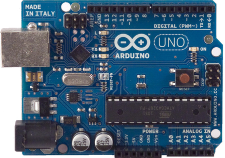
There is a neat store near his house called Gateway Electronics.  They have pretty much everything you could want for electronic projects for good prices (and free Twizzlers).  I bought an Arduino Uno, a continuous operation servo, and a couple of potentiometers.  My nephew bought the DFRobot Arduino LCD keypad shield for his Arduino.  We spent the rest of the day trying to get the Arduinos working with LCD displays and the servo.

Adafruit has a web page that explains how to connect an Arduino to an LCD.  The LCD in the example was a 16x2 LCD.  I had an LCD display from the Milwaukee Makerspace.  It looks like most LCDs are the same.  They have 14 or 16 pins.  Pin one is ground.  Pin two is power in.  Pin three is to control contrast.  Pins 15 and 16 control the backlight, if the LCD has that feature.  Pins 4 through 14 are to send data to the LCD.  Check out the Adafruit web page for more details.

The Arduino IDE comes with several example programs for displaying on an LCD.  Plus, there is a built-in library called LiquidCrystal that makes it very easy to work with LCDs.  The Adafruit page does a good job explaining the basics for first-time users like me.

Our first try at connecting the Arduino to the LCD was a bit flaky.  The display would go a bit crazy after the first boot-up.  If we wiggled the cables, the display would change.  We replaced all of the cables with different ones and the LCD worked perfectly.

Various web pages say that a potentiometer is needed to control the contrast.  You can see it in the picture above next to the right-hand corner of the LCD.  It basically needs power and ground on the outside pins.  The middle pin connects to the contrast pin on the LCD.

My nephew hooked his DFRobot LCD shield to his Arduino.  Their web page has some sample code.  He downloaded the code to the Arduino and the board worked great -- at first.  After about 30 seconds, the display started getting flaky.  Tapping on the screen would settle it momentarily.  Everything works functionally, but the display is not stable.  Looks like he will have to exchange it for a better one.

Next, I hooked the servo to the Arduino.  I found an Arduino sketch to control the servo with pulse width modulation.  It basically lets you press keys on the computer keyboard to speed up and slow down the servo.  I played around with the minimum and maximum settings and was able to get the servo to go both clockwise and counter clockwise.  I also added the LCD code to the sketch to display the pulse width setting on the screen.  Nice!

The Arduino IDE comes with a library for the servo called the Servo Library.  I did not play with the Library much but I was able to get it to go clockwise, counterclockwise, and stop.  The library did not control the time, nor the speed.  Maybe it will, but I could not get it to work that way.

In the picture to the right, you can see the Arduino in the front, the LCD in the middle, and the servo in the rear.  I would like to use the Servo to control the automated pet food dispenser.  In theory, I could connect the Arduino to the servo and plug the power for the Arduino to a timer that will turn it on once or twice a day for five minutes.  The program I wrote moves the augur counter-clockwise for about 1 second.  Then, it rotates clockwise for 2 seconds.  According to the Instructable about the dispenser, this will keep the augur from jamming on food pieces.  One weird thing is that the program works great when the Arduino is connected to the PC but not when it is connected to a USB power converter.

Here is the code to control the servo.

#include <server.h>

Servo augur; 

void setup() 


void loop()

  // Make the servo turn clockwise then counter 
  // Set up the servo 
  augur.attach(9); 

  // Spin counter clockwise 
  augur.write(-180); 
  delay(1000); 

  // Spin clockwise 
  augur.write(180); 
  delay(2000); 

  augur.detach(); 
  delay(500); 
}

Friday, November 8, 2013

Pitcher Holder "Fixed"

The pitcher holder piece that I 3D printed for the automated pet food dispenser does not fit correctly on to the PVC T.  The inside diameter of the pitcher piece is just a bit too small.

I used a drill press and various tools at the Milwaukee Makerspace to rough out a bit of the inside diameter of the part.  I tried different tools (see picture) starting with a little Dremel sander (not pictured), then a 1/4" drill bit, a bigger gear-looking bit, and finally, a wire brush.  The sander and wire brush both worked but are incredibly slow.  The drill bit did not work at all.  The gear thing was too coarse.  It kept gouging out parts of the plastic.

Eventually, I did shave off enough plastic to squeeze the holder onto the PVC.  Unfortunately, I shaved off enough plastic to get to the inlay and crack the piece.  You can see the crack in the picture of the piece.

I will see what Tim thinks but we will probably push on and try to finish assembly with what we have as a beta.  Then, I can re-measure everything and try to re-size and re-print the auger and pitcher holder to fit the PVC dimensions.

I think that will be after I get the HESA project done.

Thursday, November 7, 2013

Pet Feeder Assembly Started

Tim and I started to assemble the automated pet feeder parts.

Actually, before we started, I went to Home Depot and bought a 2" circular wire brush that can be inserted into a drill.  Tim and I spent some time using it to smooth out the inside of the PVC T.  After many minutes with the drill, most of the raised part is gone but there were still some higher spots.

We then tried shaving off some of the other auger piece to make the circumference smaller.  That did not turn out so well.  During the process, a bigger part of one edge was cut off.  Then, one of the parts near one end broke off.  Even though it seemed like we cut off quite a bit of the auger, it still sticks a bit in some spots.

We did start assembling the pieces to see how it looks and to feel like we are making progress.  See the pictures.  A pitcher to hold the dog food would go on top of the blue part (that does not fit on the PVC either).  The servo would be attached to the white piece that is attached to the wood support.

I think that I will continue to try smoothing out the inside of the T.  Also, I have an extra auger that was not printed perfectly.  I think I will use that one instead of the broken one.  Hopefully, it will fit in the T if I can get it smoothed down.

Another idea would be to use a plunger instead of an auger.  Maybe that would be more reliable.  I'll have to see if I can find a device to push a cylinder through the PVC.

Finally, now that I've got some experience with this, I would do a few things differently.  First, I would purchase the PVC T and figure out the servo and controller before starting to make anything.  That way, I could measure the PVC and possibly adjust some of the prints and cuts.  Also, knowing what the servo would look like would help to know what kind of end piece would be needed to attach the servo to the wood support.

Tuesday, November 5, 2013

PVC T for Pet Food Dispenser

Over the weekend, I bought a 2" PVC T and the hardware to assemble the pet food dispenser.  When I got home, I tried inserting the PVC into the wood supports that I cut on Friday.  The hole was just a bit too small.  My theory is that we should have made the cut for the hole right on the line instead of on the inside of the line.

Next, I tried putting the augur in the T.  It went in the first few inches just fine.  Then, it hit the raised part that is made to step the PVC that is inserted into the T.  Doh!  The augur was sized for a 2" diameter but the inside of the PVC is about 1 3/4" with the raised part.  Strike two.

First, I went to Home Depot and bought a different PVC T.  This one still had a raised part inside but it was about half as thick as the other T.  I was hoping it would be easier to make it work.

Then, Tim and I stopped off at the Makerspace to fix the two problems.  We put an abrasive disc Dremel part into a drill press and used that to make the holes on the wood bigger.  It took a few passes to get it right.  Now, the PVC T fits snugly into the wood supports.

Once that was done, we turned our attention to the augur.  At first, we tried getting rid of the raised part on the inside of the T.  We used a hand file and spent a good bit of time with that.  It did make some difference but not enough.  One problem is that the file was flat and the inside of the PVC is round so there was not enough surface area contact.

Finally, we used a band sander to remove a layer off of one of the auger halfs.  That was very ugly but it seemed to work.  I only brought one auger half so we could not finish the job.

After we left, I thought that we should have used a circular wire brush attachment for a drill.  I did not see one at the space.  Maybe I will go to Home Depot and buy one and then use it to smooth out the inside of the T.  I might also have to re-print the augur parts if they will then fit on the inside of the T.

I will chalk this up to a learning experience.

Friday, November 1, 2013

First CNC Router Cut

I spent the evening at the Milwaukee Makerspace.  Tonight I learned how to use the CNC router.  Brant, the President of the 'space spent over an hour training me.  (Thanks Brant!)

I used the CNC router to cut the wood support pieces for the automated pet food dispenser.  The very first thing you need to cut something on a CNC router is a drawing.  The thing you want to make is designed in a 2D software application like SolidWorks, AutoCAD, or Google Sketch.  The application needs to output the results in STL format.  Fortunately, I was able to get the STL file for the wood supports from the Instructables page.

The next step is to load the STL file into a program called CamBam.  CamBam takes CAD drawings and converts them into a script (called G Code) that the CNC software can understand.  Brant and I played around a bit with the settings.  At first, CamBam was confused about how to cut the outside of the piece.  We had to combine all of the individual line segments that made up the outer edge into one long line to make it easier to follow.  Brant spent a lot of time showing me all of the settings in the software.  We got everything working so the machine would cut the hole in the middle, make small indentations for the screw holes, and cut out the entire piece.  The last step was to save all of the commands required to cut the piece as a G Code file.

The G Code text file was loaded into a program called Mach3.  Mach3 is the software that actually controls the CNC router.  It processes the G Code line by line, sends signals to the CNC router and processes the results.  We also had a small amount of setup to do in Mach3.  Basically, we had to center the router in the correct position and height to do the cut completely within the piece of wood.  That only took a few minutes and we were underway.

We programmed the CNC machine to make three passes of .25 inches each.  In hindsight, maybe it should have made more passes.  That might have kept the wood from getting torn up.  The total cut time was only about three minutes per piece.  After the first cut was done, we moved the bed, re-zeroed the router, and cut the second piece.

Here is a link to a short (and somewhat boring) video showing the first cut on the CNC router.  As you will see, we had to hold down the piece when it made the indentations for the small holes.  We fixed that on the second cut by adding more holding tabs and also cut the outline of the entire piece last.

After cutting both pieces, I sanded them and then drilled the small holes for the screws.

I have finished making all of the pieces for the dispenser.  Now, Tim and I need to put it together.

Another great day at the Makerspace.

Saturday, October 26, 2013

3D Printing for Dispenser and Getting Back to HESA

Last night, I stopped off at the Milwaukee Makerspace to do a couple of things.

The first thing I did is 3D print the pieces that connect to the wood supports on the automated dog feed dispenser that I am making.  The 3D printer initially had PLA filament in it.  I tried printing with the PLA and it did not work well at first.  The raft printed ok but after that, no plastic was getting laid down.  I cancelled the print, removed the PLA and loaded some ABS filament that I had used before.  I was then able to print the two support pieces.  These are the last two pieces that I needed to 3D print.  Next, I need to use the CNC router to cut the wood.

While I was waiting for the two pieces to print (just over two hours), I got the Home Environmental Sensor Array project off of the shelf and started working on it again.  It took me about thirty minutes to get back up to speed and remember how everything was connected.  Almost everything worked.  The one thing that is not working is the sensor part of the circuit.  As soon as the wire from the sensor is connected to the input GPIO on the raspberry pi, the program I wrote shuts off power as if it detected power coming in to the GPIO port.

I don't understand why this is happening.  Tom G. from the Makerspace suggested that I add a resistor into the circuit.  I did that but it did not help.  Maybe I wired it up wrong.

I also read an article about reading a sensor on the pi.  Its not exactly the same thing I am trying to do but maybe the same circuit would work for me.  It has a resistor and a capacitor.  Maybe waiting for the capacitor to charge is a better way to detect the closed circuit.

I will try to document the circuit I am using now and post it to the Makerspace user forums.  Maybe someone will know what I am doing wrong.

I also need to publish my python source code on the internet and add links to it on my project wiki page.

Even though I did not make much progress on the HESA, it was another great day at the Makerspace.

Friday, October 11, 2013

Printed Auger Part 2

I went to the Makerspace tonight to try printing more of the pet feeder pieces.  At first, I could not get the printer to print.  Nothing would stick to the surface.

I went to get something to eat and ended up at a diner across the street from the 'Space with two other Makers.  One of the guys, Ed, knows quite a bit about the Makerbot 3D printer.  When we got back to the 'Space, he analyzed the problem.  He took the left extruder apart and realized that there was a missing washer on the pin that pushed the filament to a gear.  The missing washer allowed the gear to slip on the filament.  We added one washer and tried another print.  It worked great.

Here is a picture of half of the auger that I printed.  I realized after it started that I already successfully printed this piece and did not need another one.  Oh well.

In other news, I brought a bent metal piece that attaches to my camper to the space.  Dan, the blacksmith, helped me straighten it out.  Cool!

Another great day at the Makerspace.

Friday, September 20, 2013

Pet Feeder and Rocket Launcher Updates

This is actually the second time I have been at the Makerspace since I got from vacation.

Last week, I spent a few hours using the Makerbot Replicator 3D printer to print two more pieces for the automated pet food dispenser.  One was the second half of the auger and the other was a piece to attach the auger to the wood are done (pictured to the right).  However, once I took the auger half home and married it up to the other half, I realized that the first half did not print perfectly.  It curled up a bit on the edges.  So, the halves do not have a lot of surface area that touches and may not glue together well.

This week, I tried re-printing the first half of the auger piece.  I could not do it.  The filament would not stick to the plate.  I tried leveling the plate, cleaning the plate, removing and re-loading the filament, printing from both extruders; nothing worked.  After about an hour of messing around, I gave up.

After punting with 3D printing, I worked on the rocket launcher.  I soldered in the switch I had found and tested the launcher.  The LED stayed on no matter which position the switch was in -- on or off.  I tested the switch by using a multimeter to test the resistance of the switch in both the on and off positions.  The test showed that the switch was stuck open.

I found another switch in the parts rack at the Makerspace and soldered that in to the launcher box.  This time, it worked perfectly.  I used a small motor as a test object in place of an actual rocket.  When I hooked the wires to the motor, the LED lit up -- great.  Then, when I pushed the launch button, the LED went off and the motor fired up.  Next step is to test with an actual rocket.

In other news, the computer that is in the 3D printer area would not turn on.  Long-story-short, we replaced the power supply with a spare we found on the hack rack and now it works.