One feature of the HESA program is that it checks to see if it can connect to the internet before trying to make an update. It does this because it will throw an error and kick out of the program if it can't write to the database because the internet is down.
There is a built-in python function to check for internet access. The code looks like this.
urllib2.urlopen(reference, timeout=1)
The URL I use as a reference is 74.125.228.100. That IP address is supposed to be one of google's mail servers. I figured it would be available forever. However, about a week ago, it stopped responding to the python command and pings.
I did a quick search on the internet about the best IP address to use to test if the internet is up. This site recommended using 8.8.8.8. That is Google's DNS server. Another good idea is to use Open DNS's DNS server IP address.
I made simple test program that uses the urlopen function. I sent both the 74.125 and 8.8 addresses to the function. It could not find the internet with either address.
Then, I used the function to look for http://google.com. The function found that address. So, the python function does not work with IP addresses.
I changed the code to always look for google.com. Now, it is seeing the internet. Problem solved.
The purpose of this blog is to record my progress on maker projects that I am working on. I will tag each post with the name of the project to group posts together.
Advertisement
Showing posts with label Home environmental sensor array. Show all posts
Saturday, April 25, 2015
Friday, January 23, 2015
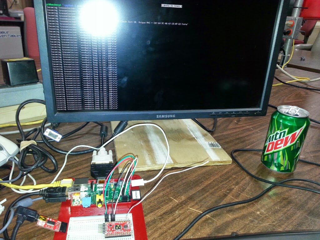
Moteino to Raspberry Pi over Serial v3
I was able to get my Moteino host talking to my Raspberry Pi over the Pi's serial port. Last time, it was working but the information coming over did not make sense. The problem was in my sprintf statement in the Arduino sketch. I had a %d parameter in the command. Text was getting converted to numbers. I replaced the %d with a %s and now the sketch sends the correct data to the Pi.
After some experimentation, it looks like the problem was the time it took for the Moteino to blink the LED. After each receipt, I was blinking the LED three times with a 100ms pause between each on-off cycle. That was apparently too much time. The middle transmission was getting lost. I turn the blinking down to one per transmission and the host now receives all transmissions.
Also, the node was sending all three transmissions with three LED blinks with a 100ms pause. I set the blinks to one per transmission and the host could once again not keep up.
I changed the node to blink once per transmission and pause for 150ms. This limited transmissions to one every 1/4 of a second. The host was able to read those.
After all of this, I set the node to only transmit one piece of data every five seconds. That way the HESA will have time to process each reading.
More time experimenting
The HESA takes 10 seconds to look for water. Plus, it needs a few seconds to get the temperature and humidity readings from the DHT22. Finally, it has to update the web page every hour. That takes a few seconds.
I set my test program on the Pi to sleep for ten seconds if there is nothing in the serial's input buffer. I also set the node to send some data every few seconds. When I do that, the host misses 2/3 transmissions each cycle. That is not good. Here is the code I am using:
import serial
import time
port = serial.Serial("/dev/ttyAMA0", baudrate=115200, timeout=3.0)
while True:
rcv = ''
while port.inWaiting() > 0 :
rcv = port.readline(255).strip();
if (rcv != "") :
print ("Incoming transmission: " + rcv);
else :
print ("Sleeping");
time.sleep(10);
I tried something different. I set the timeout to 0 and read the port every ten seconds. Here is the code in this case:
import serialimport timeNow, the program reads all of the data in the buffer, but it reads it as one big string. Since I am sending the data in three transmissions with EOL, the data looks like this:
port = serial.Serial("/dev/ttyAMA0", baudrate=115200, timeout=0.0)
while True: rcv = '' rcv = port.read(9999)
if len(rcv) > 0 : print ("Incoming transmission: " = rcv);else : print ("Sleeping"); time.sleep(10);
Incoming transmission: 002|101~3369.00
002|102~68.00
002|103~35.00
I will change the node program to do one transmission with all data in one long string. That is for another day.
Friday, January 16, 2015
Connect to Raspberry Pi Over Serial Connection
Tonight at my weekly me time at the Milwaukee Makerspace, I am going to attempt to get my Moteino connected to my Raspberry Pi using the serial connection on the Raspberry Pi. Also, to be a bit different, I am going to try to take notes on the blog as I go. This will either help me take better notes or make this blog entry completely unintelligible to any reader who does not think like me.
There are instructions to work with the Raspberry Pi's serial port at this web page: http://elinux.org/RPi_Serial_Connection. I scrolled down to the section titled "Connection to a microcontroller or other peripheral". There are several things to do to stop the Linux kernel from using the serial port. This is a prerequisite. It looks like there is a script someone made to do all of these things automatically. I am going to try to do the steps myself.
I edited the /boot/cmdline.txt file. Also, commented out a line in /etc/inittab that opens a login prompt ("getty") on the serial port.
Rebooted. Logged in with no problems. There are two checks on the web page that you can run to verify that you did it right. Both checks passed.
The next step is to try interacting with the serial port using Python code. I installed the PySerial package by typing
This page has a very small python program to test the serial connection. I used nano to create it.
The first test I did was to connect the Raspberry Pi's serial pins to the serial pins on the Moteino --
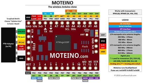
Tx to Rx, Rx to Tx, and Gnd to Gnd. Then, I connected the Moteino to my Linux laptop using the FTDI adapter. I loaded the Arduino IDE on the laptop, uploaded the HESA_Host sketch, plugged in the USB to the Moteino, and ran the python program. Nothing happened. I don't know if the problem was that the Moteino does not know what to do when there are two serial connections or if my sketch is bad.

The next test I did was to bypass the Moteino and connect the serial wires from the Raspberry Pi directly to the FTDI adapter. That test worked. The terminal screen on the Arduino displayed the output from the Pi and the Pi received the text I typed in on the terminal screen. Cool!
Tried again with the FTDI connected to the Moteino and the Moteino connected to the Pi. Made some small modifications to the sketch and tried uploading it to the Moteino. The sketch would not upload.
Unplugged the TxRx wires from the Pi. Now, the sketch will upload.
For the next test, I changed the python code so it will send the letter "t" to the serial port every second, read the results on the serial port, and print the results, if any to the screen. I also connected a wire from one of the 5v outputs on the Pi to the VIn pin on the Moteino. I ran the python code and it worked perfectly. The Moteino faithfully sent its temperature back to the Pi everytime it received a T.
Time to try the whole solution. I setup my node with the DHT11 temperature sensor. Then, I started the python program and waited a few seconds. Next, I powered up the Moteino host. It transmitted its messages from the setup part of the sketch. Finally, I powered up the Moteino node. It started transmitting its data every few seconds. Everything worked. The host received the transmissions and sent them to the Raspberry Pi. The python program displayed the transmissions on the screen.
One problem is that it looks like the python program started displaying the ascii text as hex characters, ex. 0\xe0\x00. That seems to have started after it received a "]" character.
Tried changing the baudrate on both devices to 9600. That did not help.
Tried adding a \n to the end of each transmission to the serial port. That did not help.
Tried putting a 1ms delay after every transmission. That did not help.
The weird thing is that if I send a T to the Moteino, the sketch returns the temperature text with no problems. Anything else looks like hex.
Figured it out. I had some code in the sketch turn off the Moteino in between transmissions to save power. This was the cause of the garbled code. Turning off the power save feature fixed the problem. I don't really need the power save feature since the host Moteino will get power from the Pi.
The new problem is that the data being sent to the PI does not appear to be the data the node is sending. The data should be something like "002|102~87", but it is some other combination of number. I'll have to look into that later.
Also, need to figure out how to know when a batch of data is from one node. Maybe I could put some text around each end of the package. For example, ">>>002|102~67<<<".
I'll have to figure that out some other time. That's enough for one night.
There are instructions to work with the Raspberry Pi's serial port at this web page: http://elinux.org/RPi_Serial_Connection. I scrolled down to the section titled "Connection to a microcontroller or other peripheral". There are several things to do to stop the Linux kernel from using the serial port. This is a prerequisite. It looks like there is a script someone made to do all of these things automatically. I am going to try to do the steps myself.
I edited the /boot/cmdline.txt file. Also, commented out a line in /etc/inittab that opens a login prompt ("getty") on the serial port.
Rebooted. Logged in with no problems. There are two checks on the web page that you can run to verify that you did it right. Both checks passed.
The next step is to try interacting with the serial port using Python code. I installed the PySerial package by typing
sudo apt-get install python-serialat the prompt. While the install was running, I noticed a message saying that there were some packages that were no longer used that could be uninstalled. I ran
sudo apt-get autoremoveto get rid of those packages.
This page has a very small python program to test the serial connection. I used nano to create it.
The first test I did was to connect the Raspberry Pi's serial pins to the serial pins on the Moteino --
The next test I did was to bypass the Moteino and connect the serial wires from the Raspberry Pi directly to the FTDI adapter. That test worked. The terminal screen on the Arduino displayed the output from the Pi and the Pi received the text I typed in on the terminal screen. Cool!
Tried again with the FTDI connected to the Moteino and the Moteino connected to the Pi. Made some small modifications to the sketch and tried uploading it to the Moteino. The sketch would not upload.
Unplugged the TxRx wires from the Pi. Now, the sketch will upload.
Time to try the whole solution. I setup my node with the DHT11 temperature sensor. Then, I started the python program and waited a few seconds. Next, I powered up the Moteino host. It transmitted its messages from the setup part of the sketch. Finally, I powered up the Moteino node. It started transmitting its data every few seconds. Everything worked. The host received the transmissions and sent them to the Raspberry Pi. The python program displayed the transmissions on the screen.
One problem is that it looks like the python program started displaying the ascii text as hex characters, ex. 0\xe0\x00. That seems to have started after it received a "]" character.
Tried changing the baudrate on both devices to 9600. That did not help.
Tried adding a \n to the end of each transmission to the serial port. That did not help.
Tried putting a 1ms delay after every transmission. That did not help.
The weird thing is that if I send a T to the Moteino, the sketch returns the temperature text with no problems. Anything else looks like hex.
Figured it out. I had some code in the sketch turn off the Moteino in between transmissions to save power. This was the cause of the garbled code. Turning off the power save feature fixed the problem. I don't really need the power save feature since the host Moteino will get power from the Pi.
The new problem is that the data being sent to the PI does not appear to be the data the node is sending. The data should be something like "002|102~87", but it is some other combination of number. I'll have to look into that later.
Also, need to figure out how to know when a batch of data is from one node. Maybe I could put some text around each end of the package. For example, ">>>002|102~67<<<".
I'll have to figure that out some other time. That's enough for one night.
Saturday, January 3, 2015
Moteino Node Talking to Host
After about two weeks off for the holidays, I spent time at the Milwaukee Makerspace working on the Moteinos for my Home Environmental Sensor Array.
3D Print of a Battery Holder
As part of the node solution for the HESA, I want to have a complete stand-alone package that includes a holder for the battery. Also, I want to have 6v battery for the power supply since the Moteino needs at least a 3.2v input.
I have a 6v Lithium battery from Energizer. I made a case for it but it is not ideal and not reproducible. I found a Thing on Thingiverse to 3D print a holder for a Panasonic Lithium battery.
I printed the holder on the Cube Pro Trio 3D printer at the Makerspace. The printer is very easy to use. I was hoping it would be more reliable than the other printers we have but my first print failed. I printed the holder in draft mode and it finished but the corners pealed up a bit. Also, I found out that the Panasonic battery is longer than the Energizer and the terminals are in different spots. So, I won't be able to use the holder and will have to find a different solution.
On the plus side, I learned how to use the CubePro Trio printer. This is a professional-grade 3D printer that should make high quality prints.
ACK Testing
The last time I played around with the Moteino, the node was sending data to the host but the node was never getting an ACK back from the host. I tested combinations of all three Moteinos with the same results. I posted something on the Moteino forum and the response was that it should work. I finally got back to testing the ACK feature and was able to get it working -- sort-of.
I think the original problem is that I did not have the antennas attached to the Moteinos. I soldered antennas onto all three Moteinos, and they now send and receive ACKs properly.
However, this gets more and more unreliable as the distance between the node and host increases. When the distance is less than 20 feet, the ACKs are almost always received. At 50 feet, ACKs are received about 50% of the time. If I go over 100 yards away, almost no ACKs are received.
Finally, I created a sketch for a node on the HESA network. The sketch will read and transmit the following information to the host:
The next step is to connect the host to a Raspberry Pi and have the Pi read the serial inputs. Then, I need design a circuit board and complete solution for the node. Finally, I need to make the HESA python program on the RPi send node data to the SQL database.
3D Print of a Battery Holder
I have a 6v Lithium battery from Energizer. I made a case for it but it is not ideal and not reproducible. I found a Thing on Thingiverse to 3D print a holder for a Panasonic Lithium battery.
On the plus side, I learned how to use the CubePro Trio printer. This is a professional-grade 3D printer that should make high quality prints.
ACK Testing
The last time I played around with the Moteino, the node was sending data to the host but the node was never getting an ACK back from the host. I tested combinations of all three Moteinos with the same results. I posted something on the Moteino forum and the response was that it should work. I finally got back to testing the ACK feature and was able to get it working -- sort-of.
I think the original problem is that I did not have the antennas attached to the Moteinos. I soldered antennas onto all three Moteinos, and they now send and receive ACKs properly.
However, this gets more and more unreliable as the distance between the node and host increases. When the distance is less than 20 feet, the ACKs are almost always received. At 50 feet, ACKs are received about 50% of the time. If I go over 100 yards away, almost no ACKs are received.
I posted a message on the Moteino forum to see what the problem is. However, I also decided that I don't care about ACKs for the HESA. For now, I can continue without this feature.
HESA Node
- Notification that it is on-line on bootup
- Battery voltage
- Temperature from the RF69 chip or from a DHT sensor if installed.
- Humidity from DHT sensor if installed
The code is flexible enough to request ACKs or not when sending data. The device will also sleep between sends. This should make the battery last longer.
The next step is to connect the host to a Raspberry Pi and have the Pi read the serial inputs. Then, I need design a circuit board and complete solution for the node. Finally, I need to make the HESA python program on the RPi send node data to the SQL database.
RPI serial console: http://elinux.org/RPi_Serial_Connection
Saturday, December 20, 2014
Power Monitoring with the Moteino -- Attempt #2
This weekend at the Milwaukee Makerspace, I continued trying to get my Moteinos to communicate to each other. I want to get a node to send its power level to the host. I performed a number of tests and eventually accomplished the goal.
Basic TxRx Test
The test involved uploading the TxRxBlinky sketch on each Moteino -- one as the Receiver, and one as the Sender. I hooked a button up to the Sender. Once both Moteinos were powered up, I pushed the button on the Sender. This caused the LED on the Receiver to change state -- on to off or off to on. The Receiver also sends some text to the serial monitor.
| SENDER | RECEIVER | RESULTS |
| M3 | M2 | Passed |
| M3 | M1 | Passed |
| M1 | M2 | Passed |
| M1 | M3 | Passed |
| M2 | M1 | Passed |
| M2 | M3 | Passed |
All tests passed. All Moteinos can both send and receive. Also, they all operate with either the USB as a power source or the Lithium 6v battery as the power source.
Gateway / Node Test
For the next test, I used the Gateway / Node sketches from LowPowerLab. The Gateway sketch was loaded on the Receiver Moteino and the Node sketch was loaded on the Sender Moteino. All Moteinos were set at 915mhz frequency. The high power setting was set on all Moteinos.
Before testing a pair of Moteinos, I loaded the Node sketch on one Moteino and watched what happened with the serial monitor. The Moteino outputted exactly what it was supposed to.
Next, I uploaded the Gateway sketch to a Moteino and started testing.
| Test | Gateway | Node | Results |
| 1 | M1 | M2 | Passed |
| 2 | M3 | M2 | Passed |
| 3 | M3 | M1 | Passed |
| 4 | M2 | M1 | Passed |
| 5 | M1 | M3 | Passed |
| 6 | M2 | M3 | Passed |
All tests passed.
Custom Node Test
Now that I know all of Moteinos can talk to each other, I tested a custom node program. It is set to transmit at 915mhz. The high power setting for the RFM69HW is set.
The custom program is a modified version of the Node sketch from LowPowerLab. The sketch reads the voltage from the Moteino and transmits it to the host. (More information about the code to read the voltage is in this post.)
I had the same problem with the sketch that I had last week. If the Node program tries to read the voltage using the readVCC function, then tries to use the radio.sendWithRetry function, the Moteino appears to reboot--it is re-running the setup function. If I comment out the line that calls readVCC, the rest of the code processes normally. However, the send line prints the message indicating it failed.
After a lot of testing, I realized that the failure message I am getting is always there -- even with the code that comes with the Moteino. I ran my Node program and the Host displayed the voltage from the Node. The code works even though the failure message prints. I don't know if there is something wrong with the code or if I don't understand how the read.send function is supposed to work.
I don't know why the Moteino was rebooting. I did fix that problem by starting over with the original Node program and adding my code bit by bit. The problem did not re-occur. Maybe I had some invisible characters in the code.
Finally, I tested the voltage that is read by the node. I connected a variable power supply to the power input on the Node. This let me vary the input voltage. I started at 6 volts and slowly turned the voltage down. Sending any voltage over 3.2 registers as 3349 millivolts. Once the voltage was turned down to 3.2 volts, the device read 3205 or 3196 millivolts. When the input got down to 3.1 volts, the node stopped transmitting. So, I will be able to use this code to monitor my battery's voltage.
One of the next steps is to understand how the node and host communicate.
- Can the node sleep until the host calls it?
- If the node sends data to the host, will it get lost? Is there a way to know for sure?
- How do we make the device truly low-power?
- What does the Ack do?
Sunday, December 14, 2014
Possible Smoked Moteino
I tested the Moteino to see if anything still worked. First, I plugged in the FTDI adapter and used a USB cable to connect the Moteino to my PC. The Arduino IDE software saw the board. I uploaded the "Fade" example sketch to the Moteino. It worked.
Next, I loaded the TxRxBlinky example sketch for the Moteino. I was able to use the Moteino as a Sender device. I assume that means that the transceiver is also working.
Finally, I used a multimeter to check the voltages. The Lithium battery I had hooked up was sending 6.27 volts to the Moteino VIN pin. The 3.3 pin on the Moteino was putting out 3.31 volts. This means that the regulator in the Moteino is also working.I think everything is working. I'm going to try using this Moteino as the main receiver on my Home Environmental Sensor Array.
+Moteino
+Microcontroller
+Arduino
#Moteino, #Microcontroller, #Arduino
Saturday, December 13, 2014
Testing Moteinos
This blog post is covering my last two weeks of activity on the Moteinos for my Home Environmental Sensor Array. Topics include
Power Supply Experiments
I spent a good deal of time trying different ways to power the Moteino. I was hoping that I could use a 3v Lithium battery as a power source. That way, I could have an easily replaceable and cheap power source. However, the coin cell battery I used did not appear to provide enough power to run the Moteino.
Next, I tried a 3.6v Lithium battery that I found in the battery box at the Makerspace. It put out about 3.6 volts on its own. After connecting it to the Moteino, I used a multimeter to see how many volts were going into the Moteino. It registered at about 1.4 volts. Not sure what is happening but this battery does not provide enough power for the Moteino either.
Finally, I tried using a 6v lantern battery as a power input. That worked better. When I tested the voltage with a multimeter, it registered 6.23 volts. After I connected the battery to the Moteino, I tested the voltage by putting the test leads on the GND and VIN pins on the Moteino. It registered 6.17 volts. Since the Moteino has a built-in power regulator that limits the voltage to 3.3 volts, this is more than enough power.
In order to power nodes, the Moteino needs a power source that delivers between 5-9 volts. The two options are a 6v Lithium battery or a 9v NiCd battery. I would prefer the smaller battery because it will waste less energy when the Moteino converts the voltage to 3.3 volts.
Attaching a Power Supply to a Moteino Node
Now that I know how much power I need to supply, the next task is to figure out how to attach power to a Moteino that will operate as a stand-alone node.
I bought a 6v Lithium battery as an external power source. It is just a bit bigger than a 9v battery. Also, the power ports are recessed. This makes it difficult to attach wiring to the battery.
My first idea for a reliable power storage solution for the 6v battery was to re-use an existing 9v battery container. I found an old clock radio on the hack rack at the Milwaukee Makerspace. The radio had a space for a 9v battery built-in to one part of the plastic case. I cut out the 9v battery compartment from the case.
I settled on the idea of using screw heads to connect to the recessed battery terminals. First, I cut a small piece of balsa wood to fit into the bottom of the compartment. The wood is just a bit smaller than the compartment. The wood is just big enough to not move around. Also, when the battery is inserted into the compartment, it will keep the wood from moving.
Next, I put two screws through the wood and cut off the extra length of each screw with the metal bandsaw. Finally, I attached wires to each screw. In hindsight, I should have put the aluminum strips on the top of the wood. That would have helped the conductivity of the wires to the screws.
Putting the battery into the compartment so it has good contact with the screws is a bit tricky since I can't really see what is going on. However, once the battery is in properly, it delivers 6v. I can connect the wire leads either to a prototype board or to input pins on a circuit board. Although this does work, it is not an ideal solution. Ideally, I would like a solution that works as easily as traditional battery connectors. Either I could rig up a cap like 9v batteries have or I need a more cozy container that is a better fit for the lithium battery and makes a good connection every time a battery is inserted. Maybe I could 3D print a container.
Also, I was testing the battery with one of my Moteinos and I inadvertently attached the positive wire to the GND pin on the Moteino. The Moteino started smoking. I immediately pulled out the wire but I don't know what damage was done. When I connect the Moteino to my computer with the FTDI cable, it powers up. The Arduino IDE client sees the device. I uploaded a sketch to the Moteino that made an LED blink. I still need to test the RF device. If that works, the Moteino may not have been damaged at all. That would be a blessing.
Testing Multiple Moteinos
I purchased two more Moteinos -- one for my first node, and one for backup or the second node. The
Moteino site has a section on programming the Moteino. One of the Arduino sketches allows you to test a receiver / sender pair of Moteinos. When you press a button connected to the sender Moteino, it sends a signal to the receiver that toggles an LED -- if it is off, it turns on, and vice-versa.
I was able to successfully test this with two of the Moteinos. Now, I know a bit more about using the Moteinos. Next, I need to figure out how to connect the receiver Moteino to my Raspberry Pi. Another next step is to write a sketch to read something on the node and send it to the receiver Moteino.
- Power supply experiments
- Attaching a power supply to a Moteino node
- Testing multiple Moteinos
Power Supply Experiments
Next, I tried a 3.6v Lithium battery that I found in the battery box at the Makerspace. It put out about 3.6 volts on its own. After connecting it to the Moteino, I used a multimeter to see how many volts were going into the Moteino. It registered at about 1.4 volts. Not sure what is happening but this battery does not provide enough power for the Moteino either.
Finally, I tried using a 6v lantern battery as a power input. That worked better. When I tested the voltage with a multimeter, it registered 6.23 volts. After I connected the battery to the Moteino, I tested the voltage by putting the test leads on the GND and VIN pins on the Moteino. It registered 6.17 volts. Since the Moteino has a built-in power regulator that limits the voltage to 3.3 volts, this is more than enough power.
In order to power nodes, the Moteino needs a power source that delivers between 5-9 volts. The two options are a 6v Lithium battery or a 9v NiCd battery. I would prefer the smaller battery because it will waste less energy when the Moteino converts the voltage to 3.3 volts.
Attaching a Power Supply to a Moteino Node
Now that I know how much power I need to supply, the next task is to figure out how to attach power to a Moteino that will operate as a stand-alone node.
My first idea for a reliable power storage solution for the 6v battery was to re-use an existing 9v battery container. I found an old clock radio on the hack rack at the Milwaukee Makerspace. The radio had a space for a 9v battery built-in to one part of the plastic case. I cut out the 9v battery compartment from the case.
Next, I put two screws through the wood and cut off the extra length of each screw with the metal bandsaw. Finally, I attached wires to each screw. In hindsight, I should have put the aluminum strips on the top of the wood. That would have helped the conductivity of the wires to the screws.
Also, I was testing the battery with one of my Moteinos and I inadvertently attached the positive wire to the GND pin on the Moteino. The Moteino started smoking. I immediately pulled out the wire but I don't know what damage was done. When I connect the Moteino to my computer with the FTDI cable, it powers up. The Arduino IDE client sees the device. I uploaded a sketch to the Moteino that made an LED blink. I still need to test the RF device. If that works, the Moteino may not have been damaged at all. That would be a blessing.
Testing Multiple Moteinos
I purchased two more Moteinos -- one for my first node, and one for backup or the second node. The
I was able to successfully test this with two of the Moteinos. Now, I know a bit more about using the Moteinos. Next, I need to figure out how to connect the receiver Moteino to my Raspberry Pi. Another next step is to write a sketch to read something on the node and send it to the receiver Moteino.
Friday, November 28, 2014
Power monitoring with the Moteino -- Attempt #1
The Moteino is fully compatible with an Arduino UNO. Vishal from the 'space told me that the Arduino has the ability to determine the incoming power. There is an internal reference voltage that always measures 1.1v. This reference voltage can be used to more accurately measure the input voltage to the Arduino. Here is a web page that talks about this in more detail. That web page also has code to measure the input voltage. Below is the code that I used to measure the voltage on my Moteino. The output consistently read 3369 millivolts.
long readVCC() { // Read 1.1V reference against AVcc // set the reference to Vcc and the measurement to the internal 1.1V reference #if defined(__AVR_ATmega32U4__) || defined(__AVR_ATmega1280__) || defined(__AVR_ATmega2560__) ADMUX = _BV(REFS0) | _BV(MUX4) | _BV(MUX3) | _BV(MUX2) | _BV(MUX1); #elif defined (__AVR_ATtiny24__) || defined(__AVR_ATtiny44__) || defined(__AVR_ATtiny84__) ADMUX = _BV(MUX5) | _BV(MUX0); #elif defined (__AVR_ATtiny25__) || defined(__AVR_ATtiny45__) || defined(__AVR_ATtiny85__) ADMUX = _BV(MUX3) | _BV(MUX2); #else ADMUX = _BV(REFS0) | _BV(MUX3) | _BV(MUX2) | _BV(MUX1); #endif delay(2); // Wait for Vref to settle ADCSRA |= _BV(ADSC); // Start conversion while (bit_is_set(ADCSRA,ADSC)); // measuring uint8_t low = ADCL; // must read ADCL first - it then locks ADCH uint8_t high = ADCH; // unlocks both long result = (high<<8) | low; result = 1125300L / result; // Calculate Vcc (in mV); 1125300 = 1.1*1023*1000 return result; // Vcc in millivolts}
void setup() { // initialize serial communication at 9600 bits per second: Serial.begin(9600);}
void loop() { float voltage = readVCC(); // print out the value you read: Serial.println(voltage); }
BTW, after uploading the program to the Arduino, I opened the serial monitor by clicking on Tools, Serial Monitor. The serial monitor displays the output from the Arduino.
Next, I wanted to see what the voltage would be from an external power source, as opposed to the Moteino getting power over the USB cable. I connected 3.5v power from an adjustable power supply to the VIN pin on the Moteino. The voltage displayed by the program never changes from 3369 millivolts. I am not sure if that is because the Moteino was still taking power from the USB or if the built-in power regulator works with any power input.
I plugged my Arduino Uno into the USB port on the computer and uploaded the script. It consistently reported 5068 millivolts. Adding 3.5v power from the external power supply on VIN did not change the readings.
I need to figure out how to get the Arduino or Moteino to send data back to my computer or maybe to a Raspberry Pi without using a USB cable.
Saturday, November 22, 2014
Started Working on Moteino Wireless Sensor Node
The Home Environmental Sensor Array is basically where I want it to be at this point. It will:
HESA Phase 2
Moteino Introduction
To get started on the wireless network, I purchased a Moteino. A Moteino is "a low cost low-power open-source wireless Arduino UNO development platform clone" that also has a HopeRF RFM69 transceiver. My initial idea is to make a stand-alone sensor using the Moteino and a DHT22 temperature sensor. Since the Moteino is an Arduino UNO clone, I can write a script to have it record the temperature in a specific location and send the results wirelessly back to my Raspberry Pi every few minutes. (More about that later.)
The Moteino is made by LowPowerLab. They also sell the Moteino and many other parts. I bought one Moteino to start with along with the flash memory add-on, some header pins, and an external FTDI adapter so I can connect the Moteino to my PC with a USB cable. (I suppose I could have made my own FTDI cable. I researched making one and it seems too hard. Now that I have the adapter, I can use it with any Moteino that I buy in the future.) The Moteino comes with a strip of wire cut to the right length to serve as an antenna. Finally, I also bought an extra HopeRF RFM69 transceiver that I would like to connect to my RPi. (More on that later.)
Assembling the Moteino
I was at the Milwaukee Makerspace and used the awesome resources at the 'space to assemble the Moteino. There is not much assembly required. Basically, I just soldered the header pins to the board. I am not sure if there is a side of the Moteino that is the top but I chose the side with the RF69 transceiver as the bottom. This means that the pins that will plug into the breadboard or circuit board are on the transceiver side of the board. I put the side pins for the FTDI adapter through the holes from the top of the board.
I put solder flux on the holes where the solder would go. Flux is said to make the solder flow better. One thing that makes soldering header pins easier is to put the pins into a breadboard and then set the board on top of the pins. The pins are straight and will not move while I am soldering. Soldering the pins is pretty easy. I heat up the pin for a few seconds then touch the solder to the iron. The solder naturally seems to flow around the pin. Just make sure the hole around the pin is completely filled. One caution is: heating the pin for too long might damage the board or the breadboard.
After soldering all of the connections, I used a multimeter to test for shorts. I set the multimeter to test for resistance. Then, I put one lead on one pin, and the other lead on the pin next to it. If the pins are connected by bad soldering, the resistance would go to zero. I did not find any shorts. Huzzah!
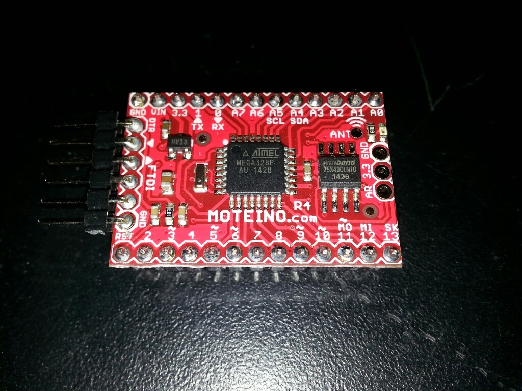
The picture below shows the FTDI adapter from LowPowerLab connected to the Moteino. The adapter makes it easy to connect a PC to the Moteino. The Arduino IDE application sees the Moteino as an Arduino Uno.
Moteino Software
The LowPowerLab website has a lot of good information about the Moteino. The guy who made the Moteino also has Arduino programming libraries on Github. The website has good information that I will not repeat here.
One thing I had to do was put the Arduino files in the proper place. I use a Linux laptop as my Maker device. So, my Arduino sketches are in the /home/kbecker/sketchbook folder. I moved the Moteino sketch folders into the libraries folder in the sketchbook folder. One thing I learned is that it does not matter what the name of the sketch folder is as long as it is in the libraries folder. I renamed the sketch folders so they start with "Moteino_". I was able to compile one of the RFM69 sketches.
Next Steps
In order to test the Moteino, I need another RFM69 transceiver. I did buy an RFM69 with the intention of connecting it to my Raspberry Pi. However, I can't find much support for that on the internet. So, I will have to figure it out myself. Physically connecting the hardware will probably not be that hard. The difficult part will be writing the software for the Pi to connect to the transceiver.
Another idea in the short-run would be to connect the RFM69 to an Arduino Uno. Then, I can use the Moteino sketches on both the base and the node just to make sure it works.
Finally, I would like to design a board for the node. The board would include the Moteino, a coin battery holder for power, connections for the sensor (DHT22 on the first one), and (if I can figure it out), a circuit to measure the power level of the battery.
I'll keep posting as I make progress. I'll also add a new project on my Makerspace wiki page.
- detect water leaks and turns on a backup pump if water is found;
- measure temperature and humidity in my basement;
- write data to a SQL database on the internet;
- send emails if it detects problems and send an "all clear" message when problems clear
The one thing I would like to do before moving on is have it record data locally if the internet is down and write it to the database after the internet connection is restored.
HESA Phase 2
However, I would also like to start on to the next phase of the project. Originally, I thought that would mean adding an LCD screen and blinking lights as well as more sensors connected to the Raspberry Pi or Beaglebone Black. But as my Maker skills have grown, I have gotten more ambitious. Now, I would like to build wireless sensor nodes that connect back to the RPi base. The nodes would collect data for things like temperature in rooms around my house and outside, monitor the freezer in the basement, etc. Ideally, I will have a true network of sensors all around my house.
Moteino Introduction
The Moteino is made by LowPowerLab. They also sell the Moteino and many other parts. I bought one Moteino to start with along with the flash memory add-on, some header pins, and an external FTDI adapter so I can connect the Moteino to my PC with a USB cable. (I suppose I could have made my own FTDI cable. I researched making one and it seems too hard. Now that I have the adapter, I can use it with any Moteino that I buy in the future.) The Moteino comes with a strip of wire cut to the right length to serve as an antenna. Finally, I also bought an extra HopeRF RFM69 transceiver that I would like to connect to my RPi. (More on that later.)
Assembling the Moteino
After soldering all of the connections, I used a multimeter to test for shorts. I set the multimeter to test for resistance. Then, I put one lead on one pin, and the other lead on the pin next to it. If the pins are connected by bad soldering, the resistance would go to zero. I did not find any shorts. Huzzah!
The picture below shows the FTDI adapter from LowPowerLab connected to the Moteino. The adapter makes it easy to connect a PC to the Moteino. The Arduino IDE application sees the Moteino as an Arduino Uno.
Moteino Software
The LowPowerLab website has a lot of good information about the Moteino. The guy who made the Moteino also has Arduino programming libraries on Github. The website has good information that I will not repeat here.
One thing I had to do was put the Arduino files in the proper place. I use a Linux laptop as my Maker device. So, my Arduino sketches are in the /home/kbecker/sketchbook folder. I moved the Moteino sketch folders into the libraries folder in the sketchbook folder. One thing I learned is that it does not matter what the name of the sketch folder is as long as it is in the libraries folder. I renamed the sketch folders so they start with "Moteino_". I was able to compile one of the RFM69 sketches.Next Steps
In order to test the Moteino, I need another RFM69 transceiver. I did buy an RFM69 with the intention of connecting it to my Raspberry Pi. However, I can't find much support for that on the internet. So, I will have to figure it out myself. Physically connecting the hardware will probably not be that hard. The difficult part will be writing the software for the Pi to connect to the transceiver.
Another idea in the short-run would be to connect the RFM69 to an Arduino Uno. Then, I can use the Moteino sketches on both the base and the node just to make sure it works.
Finally, I would like to design a board for the node. The board would include the Moteino, a coin battery holder for power, connections for the sensor (DHT22 on the first one), and (if I can figure it out), a circuit to measure the power level of the battery.
I'll keep posting as I make progress. I'll also add a new project on my Makerspace wiki page.
Saturday, October 18, 2014
Recent Updates to HESA
I've been spending time in small bursts recently working on the code for the Home Environmental Sensor Array.
Status Page Updated with Graphs
First of all, I updated the HESA status web page to display a graph of the current day's settings. I found some php code called PHPGraphLib that makes it easy to create graphs with PHP. In order to use PHPGraphLib, I made a new PHP page that reads today's readings from the database and puts them in an array variable. Then, the data in the array is added to the class for the graph. Finally, PHPGraphLib dynamically creates the graph as an image file on the server. The main HESA status page calls the php page with the graphing code. The PHPGraphLib page has some good documentation and was fairly easy to get going.
I also changed the HESA status web page to have a simple table with the high, low, average, and current readings for each sensor. There are links to bring up the last 48 readings for each sensor. In the future, I would like to make graphs for monthly and yearly data.
The final change I made to the Hesa status web page is to show at a glance if the HESA is working or not. It checks the last time something was written to the database. If the last update time is over an hour old, the title of the page changes. Also, the status shows up at the top of the page. Now, I can tell if the HESA is transmitting or not just by looking at the title of the web page.
Basic Design Failed. Design Changed. Backup Pump Added.
Recently, I was replacing the sump pump in my basement. While the pump was out, the water softener turned on and started dumping water into the crock. When the crock filled up, the HESA detected the water and shut off power to the water softener -- exactly as designed. What I found out, is that the water softener continues dumping water into the sink without electricity. In other words, shutting off power to the water softener does nothing. Yar!
In order to fix this design problem, I did a couple of things. First, I bought a submersible pump and battery powered sump pump but I would prefer to have a battery backup solution for the whole system.
added it to the crock. The submersible pump will move water from the crock for the basement sink to the crock for the drain tiles. The sump pump in the second crock will then move the water outside. This will help when the first sump pump fails for some reason. I still have a problem when the power in the basement fails. Yes, I could have a
Finally, I changed the programming on the HESA so the Power Switch Tail is normally off. When the HESA detects water, it sends a signal to the PST to turn it on and provide power to the submersible pump. This is the opposite of the way the HESA provided power to the PST originally but it fixes the design flaw.
Send All Clear Message
One small improvement I made is to send an "all clear" message to the email address if the water goes away. Now, when I am doing some testing, people will get a follow-up email when all is well.
HESA Not Transmitting
I have been having problems with the HESA not transmitting.
First, There were some bugs in the code that would stop the program if it could not reach the internet. I fixed those.
Next, the GFCI outlet that my network hub was plugged in to would trip on occasion. The HESA would stay running but it could not send any data to the internet. I had to fix this because the sump pump was also plugged into the same power outlet.
That GFCI outlet has a freezer plugged in to it, plus the sump pump, and a power strip with my network hub and a small clock. For some reason, the outlet would trip when the sump pump tried to run sometimes. Perhaps it was when the freezer motor was also kicking on. I solved this problem by adding a bigger outlet and a second GFCI outlet. Now, the freezer has its own 20 amp GFCI outlet. The sump pump and power strip share the other 20 amp GFCI outlet. I have not had any more problems with the GFCI outlets tripping since I made this change.
Even after these changes, once or twice a week, the HESA still stops transmitting. When I check the processes that are running, there is no HESA program. It appears that some kind of run-time bug causes the program to stop. I need to start recording everything that happens in a log file so I can see where it stops. Then, I can fix the code to handle the errors.
Until then, I made a change the /etc/rc.local file to hopefully restart the program if it fails. Here is the code.
until sudo python /home/pi/python/hesa.py; do
echo "HESA crashed with exit code $?. Respawning.." >&2
sleep 1
done
The HESA rebooted and started just fine. We'll see if this change to the rc.local file fixes the HESA from stopping or not.
Status Page Updated with Graphs
First of all, I updated the HESA status web page to display a graph of the current day's settings. I found some php code called PHPGraphLib that makes it easy to create graphs with PHP. In order to use PHPGraphLib, I made a new PHP page that reads today's readings from the database and puts them in an array variable. Then, the data in the array is added to the class for the graph. Finally, PHPGraphLib dynamically creates the graph as an image file on the server. The main HESA status page calls the php page with the graphing code. The PHPGraphLib page has some good documentation and was fairly easy to get going.I also changed the HESA status web page to have a simple table with the high, low, average, and current readings for each sensor. There are links to bring up the last 48 readings for each sensor. In the future, I would like to make graphs for monthly and yearly data.
The final change I made to the Hesa status web page is to show at a glance if the HESA is working or not. It checks the last time something was written to the database. If the last update time is over an hour old, the title of the page changes. Also, the status shows up at the top of the page. Now, I can tell if the HESA is transmitting or not just by looking at the title of the web page.Basic Design Failed. Design Changed. Backup Pump Added.
Recently, I was replacing the sump pump in my basement. While the pump was out, the water softener turned on and started dumping water into the crock. When the crock filled up, the HESA detected the water and shut off power to the water softener -- exactly as designed. What I found out, is that the water softener continues dumping water into the sink without electricity. In other words, shutting off power to the water softener does nothing. Yar!
added it to the crock. The submersible pump will move water from the crock for the basement sink to the crock for the drain tiles. The sump pump in the second crock will then move the water outside. This will help when the first sump pump fails for some reason. I still have a problem when the power in the basement fails. Yes, I could have a
Finally, I changed the programming on the HESA so the Power Switch Tail is normally off. When the HESA detects water, it sends a signal to the PST to turn it on and provide power to the submersible pump. This is the opposite of the way the HESA provided power to the PST originally but it fixes the design flaw.
Send All Clear Message
One small improvement I made is to send an "all clear" message to the email address if the water goes away. Now, when I am doing some testing, people will get a follow-up email when all is well.
HESA Not Transmitting
I have been having problems with the HESA not transmitting.
First, There were some bugs in the code that would stop the program if it could not reach the internet. I fixed those.
That GFCI outlet has a freezer plugged in to it, plus the sump pump, and a power strip with my network hub and a small clock. For some reason, the outlet would trip when the sump pump tried to run sometimes. Perhaps it was when the freezer motor was also kicking on. I solved this problem by adding a bigger outlet and a second GFCI outlet. Now, the freezer has its own 20 amp GFCI outlet. The sump pump and power strip share the other 20 amp GFCI outlet. I have not had any more problems with the GFCI outlets tripping since I made this change.
Even after these changes, once or twice a week, the HESA still stops transmitting. When I check the processes that are running, there is no HESA program. It appears that some kind of run-time bug causes the program to stop. I need to start recording everything that happens in a log file so I can see where it stops. Then, I can fix the code to handle the errors.
Until then, I made a change the /etc/rc.local file to hopefully restart the program if it fails. Here is the code.
until sudo python /home/pi/python/hesa.py; do
echo "HESA crashed with exit code $?. Respawning.." >&2
sleep 1
done
The HESA rebooted and started just fine. We'll see if this change to the rc.local file fixes the HESA from stopping or not.
Friday, September 5, 2014
phpMyAdmin Works on HESA
I spent Labor Day weekend working on the Home Environmental Sensor Array on my Raspberry Pi. I want to start reading and writing data on MySQL tables on the Raspberry Pi. In order to make this easier, I need to use phpMyAdmin on my laptop to manage the MySQL databases on the Raspberry Pi. There were several things I had to do to get this working.
First, phpMyAdmin tries to only connect to the MySQL server on the localhost. I found a web page that explained how to get phpMyAdmin to connect to MySQL on another device. Basically, I had to edit the config.inc.php file in the /etc/phpmyadmin folder. The lines below were added after the section like it that setup the localhost connection.
Next, I had to go to the Raspberry Pi and tell MySQL to allow connections on the public internet connection and port 3306. This is done by editing the /etc/mysql/my.cnf file and changing the bind-address variable in the [mysql] section to the local IP. In my case, it looked like this:
First, phpMyAdmin tries to only connect to the MySQL server on the localhost. I found a web page that explained how to get phpMyAdmin to connect to MySQL on another device. Basically, I had to edit the config.inc.php file in the /etc/phpmyadmin folder. The lines below were added after the section like it that setup the localhost connection.
$cfg['Servers'][$i]['verbose'] = 'HESA';$cfg['Servers'][$i]['host'] = 'hesa.local';$cfg['Servers'][$i]['port'] = '3306';$cfg['Servers'][$i]['connect_type'] = 'tcp';$cfg['Servers'][$i]['extension'] = 'mysqli';$cfg['Servers'][$i]['compress'] = FALSE;$cfg['Servers'][$i]['auth_type'] = 'cookie';$i++;One thing to note is that these lines can be added to this file for every server that you want to control with this copy of phpMyAdmin.
Next, I had to go to the Raspberry Pi and tell MySQL to allow connections on the public internet connection and port 3306. This is done by editing the /etc/mysql/my.cnf file and changing the bind-address variable in the [mysql] section to the local IP. In my case, it looked like this:
bind-address = 192.168.0.58Finally, I had to setup security for the users in MySQL. I started up the mysql command line tool and executed a command like this:
GRANT ALL PRIVILEGES ON *.* TO 'USERNAME'@'%' IDENTIFIED BY 'PASSWORD' WITH GRANT OPTION;Now that I am documenting all of this, it seems pretty simple. Its hard to believe that I spent so much time trying to get this to work. Here is the end result. Now, there is a Server Choice dropdown that shows all the servers, I can connect to from my laptop.
After getting this working, I created tables for the data that I store on the rynok.org website. I also mostly copied data from the production site to the database on the Raspberry Pi. The RJ comments table did not fully copy. There is probably something wrong with the variable size for the id column. I'll deal with that later.
Subscribe to:
Posts (Atom)