- Power supply experiments
- Attaching a power supply to a Moteino node
- Testing multiple Moteinos
Power Supply Experiments
 I spent a good deal of time trying different ways to power the Moteino. I was hoping that I could use a 3v Lithium battery as a power source. That way, I could have an easily replaceable and cheap power source. However, the coin cell battery I used did not appear to provide enough power to run the Moteino.
Next, I tried a 3.6v Lithium battery that I found in the battery box at the Makerspace. It put out about 3.6 volts on its own. After connecting it to the Moteino, I used a multimeter to see how many volts were going into the Moteino. It registered at about 1.4 volts. Not sure what is happening but this battery does not provide enough power for the Moteino either.
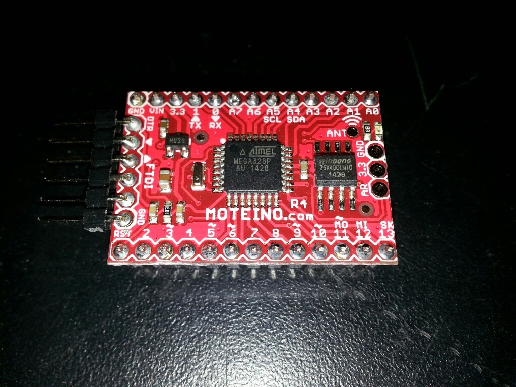
Finally, I tried using a 6v lantern battery as a power input. That worked better. When I tested the voltage with a multimeter, it registered 6.23 volts. After I connected the battery to the Moteino, I tested the voltage by putting the test leads on the GND and VIN pins on the Moteino. It registered 6.17 volts. Since the Moteino has a built-in power regulator that limits the voltage to 3.3 volts, this is more than enough power.
In order to power nodes, the Moteino needs a power source that delivers between 5-9 volts. The two options are a 6v Lithium battery or a 9v NiCd battery. I would prefer the smaller battery because it will waste less energy when the Moteino converts the voltage to 3.3 volts.
Attaching a Power Supply to a Moteino Node
Now that I know how much power I need to supply, the next task is to figure out how to attach power to a Moteino that will operate as a stand-alone node.
 I bought a 6v Lithium battery as an external power source. It is just a bit bigger than a 9v battery. Also, the power ports are recessed. This makes it difficult to attach wiring to the battery.
 My first idea for a reliable power storage solution for the 6v battery was to re-use an existing 9v battery container. I found an old clock radio on the hack rack at the Milwaukee Makerspace. The radio had a space for a 9v battery built-in to one part of the plastic case. I cut out the 9v battery compartment from the case.
 I settled on the idea of using screw heads to connect to the recessed battery terminals. First, I cut a small piece of balsa wood to fit into the bottom of the compartment. The wood is just a bit smaller than the compartment. The wood is just big enough to not move around. Also, when the battery is inserted into the compartment, it will keep the wood from moving.
 Next, I put two screws through the wood and cut off the extra length of each screw with the metal bandsaw. Finally, I attached wires to each screw. In hindsight, I should have put the aluminum strips on the top of the wood. That would have helped the conductivity of the wires to the screws.
 Putting the battery into the compartment so it has good contact with the screws is a bit tricky since I can't really see what is going on. However, once the battery is in properly, it delivers 6v. I can connect the wire leads either to a prototype board or to input pins on a circuit board. Although this does work, it is not an ideal solution. Ideally, I would like a solution that works as easily as traditional battery connectors. Either I could rig up a cap like 9v batteries have or I need a more cozy container that is a better fit for the lithium battery and makes a good connection every time a battery is inserted. Maybe I could 3D print a container.
Also, I was testing the battery with one of my Moteinos and I inadvertently attached the positive wire to the GND pin on the Moteino. The Moteino started smoking. I immediately pulled out the wire but I don't know what damage was done. When I connect the Moteino to my computer with the FTDI cable, it powers up. The Arduino IDE client sees the device. I uploaded a sketch to the Moteino that made an LED blink. I still need to test the RF device. If that works, the Moteino may not have been damaged at all. That would be a blessing.
Testing Multiple Moteinos
I purchased two more Moteinos -- one for my first node, and one for backup or the second node. The
 Moteino site has a section on programming the Moteino. One of the Arduino sketches allows you to test a receiver / sender pair of Moteinos. When you press a button connected to the sender Moteino, it sends a signal to the receiver that toggles an LED -- if it is off, it turns on, and vice-versa.
I was able to successfully test this with two of the Moteinos. Now, I know a bit more about using the Moteinos. Next, I need to figure out how to connect the receiver Moteino to my Raspberry Pi. Another next step is to write a sketch to read something on the node and send it to the receiver Moteino.
No comments:
Post a Comment