- detect water leaks and turns on a backup pump if water is found;
- measure temperature and humidity in my basement;
- write data to a SQL database on the internet;
- send emails if it detects problems and send an "all clear" message when problems clear
The one thing I would like to do before moving on is have it record data locally if the internet is down and write it to the database after the internet connection is restored.
HESA Phase 2
However, I would also like to start on to the next phase of the project. Originally, I thought that would mean adding an LCD screen and blinking lights as well as more sensors connected to the Raspberry Pi or Beaglebone Black. But as my Maker skills have grown, I have gotten more ambitious. Now, I would like to build wireless sensor nodes that connect back to the RPi base. The nodes would collect data for things like temperature in rooms around my house and outside, monitor the freezer in the basement, etc. Ideally, I will have a true network of sensors all around my house.
Moteino Introduction
 To get started on the wireless network, I purchased a Moteino. A Moteino is "a low cost low-power open-source wireless Arduino UNO development platform clone" that also has a HopeRF RFM69 transceiver. My initial idea is to make a stand-alone sensor using the Moteino and a DHT22 temperature sensor. Since the Moteino is an Arduino UNO clone, I can write a script to have it record the temperature in a specific location and send the results wirelessly back to my Raspberry Pi every few minutes. (More about that later.)
The Moteino is made by LowPowerLab. They also sell the Moteino and many other parts. I bought one Moteino to start with along with the flash memory add-on, some header pins, and an external FTDI adapter so I can connect the Moteino to my PC with a USB cable. (I suppose I could have made my own FTDI cable. I researched making one and it seems too hard. Now that I have the adapter, I can use it with any Moteino that I buy in the future.) The Moteino comes with a strip of wire cut to the right length to serve as an antenna. Finally, I also bought an extra HopeRF RFM69 transceiver that I would like to connect to my RPi. (More on that later.)
Assembling the Moteino
 I was at the Milwaukee Makerspace and used the awesome resources at the 'space to assemble the Moteino. There is not much assembly required. Basically, I just soldered the header pins to the board. I am not sure if there is a side of the Moteino that is the top but I chose the side with the RF69 transceiver as the bottom. This means that the pins that will plug into the breadboard or circuit board are on the transceiver side of the board. I put the side pins for the FTDI adapter through the holes from the top of the board.
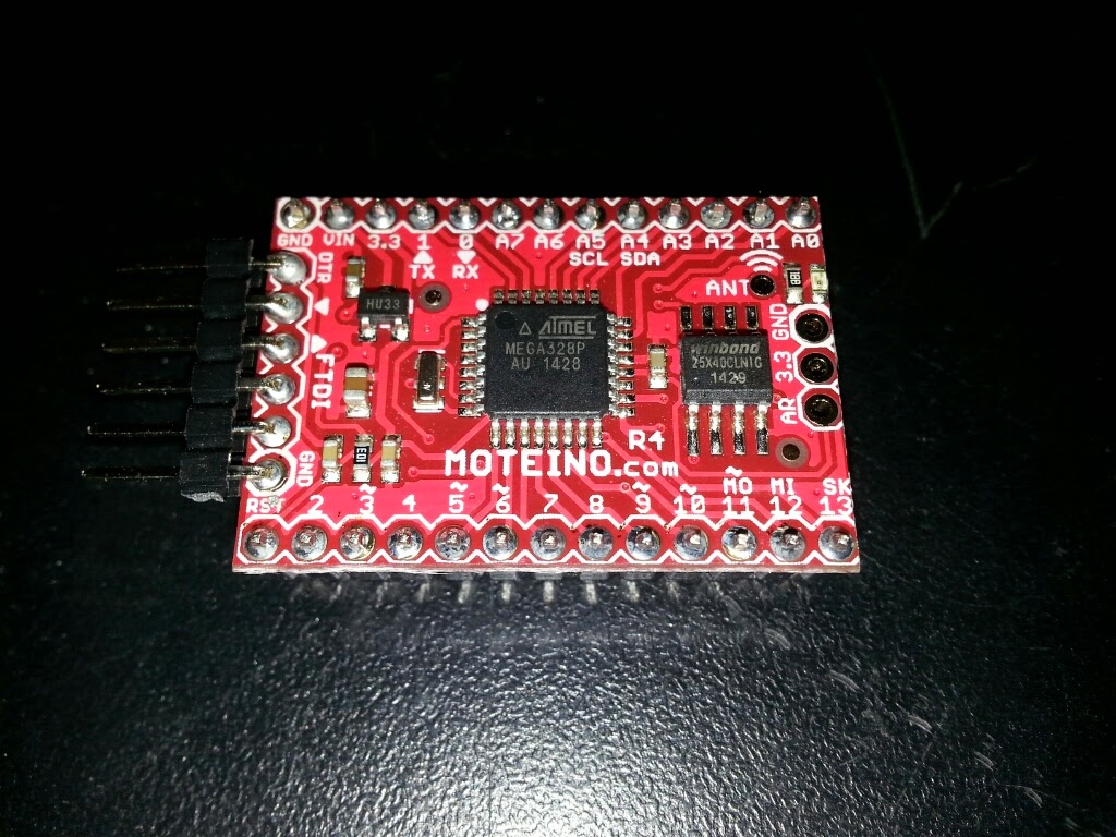 I put solder flux on the holes where the solder would go. Flux is said to make the solder flow better. One thing that makes soldering header pins easier is to put the pins into a breadboard and then set the board on top of the pins. The pins are straight and will not move while I am soldering. Soldering the pins is pretty easy. I heat up the pin for a few seconds then touch the solder to the iron. The solder naturally seems to flow around the pin. Just make sure the hole around the pin is completely filled. One caution is: heating the pin for too long might damage the board or the breadboard.
After soldering all of the connections, I used a multimeter to test for shorts. I set the multimeter to test for resistance. Then, I put one lead on one pin, and the other lead on the pin next to it. If the pins are connected by bad soldering, the resistance would go to zero. I did not find any shorts. Huzzah!
The picture below shows the FTDI adapter from LowPowerLab connected to the Moteino. The adapter makes it easy to connect a PC to the Moteino. The Arduino IDE application sees the Moteino as an Arduino Uno.

Moteino Software
The LowPowerLab website has a lot of good information about the Moteino. The guy who made the Moteino also has Arduino programming libraries on Github. The website has good information that I will not repeat here.
 One thing I had to do was put the Arduino files in the proper place. I use a Linux laptop as my Maker device. So, my Arduino sketches are in the /home/kbecker/sketchbook folder. I moved the Moteino sketch folders into the libraries folder in the sketchbook folder. One thing I learned is that it does not matter what the name of the sketch folder is as long as it is in the libraries folder. I renamed the sketch folders so they start with "Moteino_". I was able to compile one of the RFM69 sketches.
Next Steps
In order to test the Moteino, I need another RFM69 transceiver. I did buy an RFM69 with the intention of connecting it to my Raspberry Pi. However, I can't find much support for that on the internet. So, I will have to figure it out myself. Physically connecting the hardware will probably not be that hard. The difficult part will be writing the software for the Pi to connect to the transceiver.
Another idea in the short-run would be to connect the RFM69 to an Arduino Uno. Then, I can use the Moteino sketches on both the base and the node just to make sure it works.
Finally, I would like to design a board for the node. The board would include the Moteino, a coin battery holder for power, connections for the sensor (DHT22 on the first one), and (if I can figure it out), a circuit to measure the power level of the battery.
I'll keep posting as I make progress. I'll also add a new project on my Makerspace wiki page.
No comments:
Post a Comment