Advertisement

Sunday, December 29, 2013

Avahi Installed on HESA Computer

Tonight, I took a few minutes to install Avahi on the Raspberry Pi that is installed in the Home Environmental Sensor Array.  Now, I can connect to the RPi at hesa.local on my home network.  It works with ping, ssh, and to web pages hosted on the RPi with Apache.  Hopefully, it works on the network at the Milwaukee Makerspace as well.  Thanks Pete and Jason for the advice!

Here are the instructions I followed:

Executed sudo apt-get install avahi-daemon

Executed sudo insserv avahi-daemon

No messages received either way.

Executed sudo nano /etc/avahi/services/multiple.service and created a file with the text below.
<?xml version="1.0" standalone='no'?>                 
<!DOCTYPE service-group SYSTEM "avahi-service.dtd">   
<service-group>                                       
        <name replace-wildcards="yes">%h</name>       
        <service>                                     
                <type>_device-info._tcp</type>        
                <port>0</port>                        
                <txt-record>model=RackMac</txt-record>
        </service>                                    
        <service>                                     
                <type>_ssh._tcp</type>                
                <port>22</port>                       
        </service>                                    
</service-group>                                      

Executed sudo /etc/init.d/avahi-daemon restart

Saturday, December 28, 2013

LEDs for Tardis

I was at the Milwaukee Makerspace yesternight to look for LEDs and research a circuit for the LEDs to add to the Tardis.

I did find some LEDs that fit in the light holder but there weren't any white ones.  I need five ultra-bright white LEDs.  The power source will be one 9v battery.

I talked to Ron about how to figure out what resistors to use and then did some research on the internet.  I found an Instructable that explains the process.  The Instructable pointed me to a website that will calculate the resistors needed in a five LED array.

Here is one of the schematics that the website came up with.


I tested the circuit on a breadboard and it worked.  None of the LEDs blew up. 

Next, I need to get some ultrabright white LEDs.  I might even have to go to the 'Shack. 

Successfully Backed Up HESA SD Card

Now that the HESA is up-and-running, I finally made a backup of the SD card.  Basically, you use the same Win32DiskImager software that you used to install the Raspberry Pi distribution on the SD card.  Lifehacker has some good instructions for backing up the SD card.  I'm not going to repeat the instructions here.

Not only did I make a backup of the SD card to the C: drive of my computer, I installed the backup image to a new SD card and installed the copy in the Raspberry Pi.  It worked perfectly.  The RPi is running it on as you read this.  Awesome!

One interesting thing is that the original SD card was 4gb.  The copy I made went on an 8gb SD card from a different manufacturer.  I was skeptical that it would work but that was the only extra SD card I had.

By the way, I've already dropped two screws into my sump crock.  I think I need a better way to attach the acrylic to the front of the enclosure.

Wednesday, December 25, 2013

HESA program now starts automatically and updates a local web page

I made two small changes to the HESA program on my Home Environmental Sensor Array.  First, the raspberry pi will now execute the HESA program when it starts up.  No one has to be logged in for it to run.  This was accomplished by modifying the /etc/rc.local script.  I added this line to the script.

sudo python /home/pi/python/hesa.py

Also, I added some code to the python script so it will update a local web page with the current status of the HESA.  The code updates the web page every 10 minutes (more-or-less).  For now, this will let me check to make sure the HESA is working without having to go into the basement.  In phase 2, I would like to have the program update a web page on the internet and possibly a database.

HESA Installed in Basement

Today, I spent about an hour installing the Home Environmental Sensor Array in my basement.  I know.  It's CHRISTmas day.  But, I had some time before the in-laws came over for lunch, and I borrowed my brother-in-law's hammer drill over the weekend.  I wanted to use the drill and give it to my in-laws to take back with them since my brother-in-law lives near them.

I drilled two holes in the wall with the hammer drill and screwed in two screws.  I had to put nuts on the screws to keep the enclosure from falling off.  The screw heads were smaller then the opening.

After hanging the HESA on the wall, I ran a network cable from my network hub in another room in the basement to the HESA.  I did not have any male connectors so I put a CAT5 keystone jack on each end.  Then, I plugged cables in to each keystone jack.  That is not ideal but I wanted to get it done.

I plugged everything in to the enclosure and fired up the power.  All the lights on the pi turned on and blinked as expected.  I also plugged a night light in to the duplex power switch that the water softener is also plugged into.  When the night light is on, the water softener has power as well.

Finally, I connected the cable that will detect water to the bottom of the enclosure.  I started the program that looks for water and tested it.  It works!

Phase one is now 95% done.  I need to wrap up a few loose ends and then, I can move on to something else.


Saturday, December 21, 2013

HESA Enclosure Finished

Yesterday I "finished" the enclosure for the Home Environmental Sensor Array that I am building.  I say "finished" because its done enough for me to mount the HESA on the wall in my basement and turn it on.  There are always things to improve but its good enough for now.

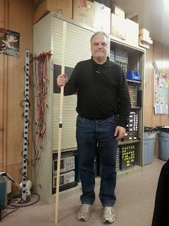
The enclosure needed some holes to install the last components.  I was at the Milwaukee Makerspace last night to work on this.  The last time I put holes in the enclosure, I drilled some starter holes and then used a hand file to remove the rest of the steel.  It took a lot of elbow grease to make two small holes.

This time, I needed to make two larger holes in the enclosure -- one for a duplex electrical outlet and one for the network outlet.  Fortunately, there were more people at the Makerspace on this Friday night.  Tom G. and Ron helped me find a better way to make the holes.  I still drilled some starter holes in the enclosure.  Then, I used Ron's Bosch Jigsaw and a metal cutting blade to cut the holes.  The holes are both simple rectangles that let the entire component fit into the enclosure.  It was fairly easy to cut the holes with the Jigsaw.  Thanks Tom and Ron for the help!

The next step was to permanently install all of the components into the enclosure.  Tom G. gave me a cool looking grey duplex outlet and metal cover plate.  I connected the outlet to the enclosure with two #6 metal screws and nuts.

I found an ethernet cable on the hack rack at the 'space and connected one end to a keystone jack from Belkin.  The only Belkin faceplate I had has four openings.  The jack went in one opening and the other three are empty for now.  I'll have to buy a single or double outlet cover to fix that.

While I was working with the enclosure, the neutral wire that was soldered to the 120v power input plug came off.  Rather then resolder it on, I removed all the wires from the plug, crimped flat blade connectors on each wire, and attached them to the plug.  Now, I can remove them easily if I want to take components out of the enclosure.  That sounds like a best practice to follow going forward.

After getting all the external connections installed, I installed the components on the inside of the enclosure.  This included the USB power supply for the Raspberry Pi, and the Pi itself.  I also had to move the Powerswitch Tail slightly to route the power cable to the duplex outlet.

At first, I was going to use standoffs to elevate the raspberry pi slightly.  However, the screw hole on the pi is smaller then the screw used in the standoff.  So, I just ended up screwing the pi directly to the wood.  I hope there are no issues with heat.

Not sure if you see it clearly in the picture but I used a piece of electrical wire and some eyehole connectors to keep the USB power supply from moving.  Its probably not a permanent solution but it helps me get this phase of the project done.

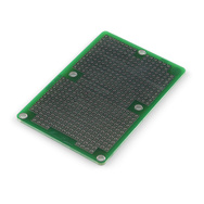
I was going to have a circuit board to go between the raspberry pi and the other parts.  However, since the water detection circuit is now rather simple, and I just want to get this phase done, and because I would probably have to replace the circuit board in phase 2 of this project, I just wired the parts directly to the pi.  I also, for no specific reason, connected the full-time 5v power to an LED that was already in the case.

After installing all of the parts, I needed to test the HESA.  Now that the pi is in the enclosure, it is difficult to connect a keyboard and monitor.  I can use ssh to remotely connect to the pi but I need to know the IP address.  There is a Linux utility called nmap that will help you find all of the devices on a network.  I installed it and then typed nmap -sP 10.1.1.0/24.  This showed me a list of all IP addresses on the Makerspace network.  I then tried connecting to the devices using ssh (ex. ssh 10.1.1.230 -l pi)  until I found my pi.  I wish I could find a way to always connect to my raspberry pi using its host name on any network I am on.  Then, I could connect with ssh right away.

The HESA works as designed.  Excellent!

Next steps.  Now that everything basically works, I need to get the enclosure installed in my basement.  I have to drill a couple of holes in the concrete blocks, put some bolts in them and then hang the enclosure on the bolts.  Next, I need to run an ethernet cable to that spot.  Then, I can do the final testing and complete phase 1 of this project.

For phase 2, I will do the following:

  • replace the raspberry pi with a Beaglebone Black.
  • install a 16x20 LCD screen in the front panel of the enclosure
  • trim the sides of the enclosure and laser etch something about HESA into it
  • add more sensors
  • add status lights (maybe)
  • make a circuit board for all of the connections
  • record readings to a database on the internet

Sunday, December 15, 2013

Fixed Some Entertainment Devices

Recently, I worked on some broken devices and got them back to working condition (more-or-less). 

First of all, I fixed a Toshiba 32“ HD LCD television that my in-laws were going to throw out.  I was able to find the owner's manual and service manual on the internet.  The service manual had troubleshooting steps that were very easy to follow.  Using my trusty multimeter, I was able to determine that the tv had a bad circuit board (p/n STW37T VTV-3707 REV:1).
Back to the internet.  I had no luck looking for the part on normal reseller pages.  Eventually, I found a used circuit board on e-bay.  I bought it and installed it in the television in about 20 minutes.  Now, the tv works great. We have tested it as a TV, hooked it up to a VCR, connected it to an HD device, and a PC. Right now, the TV is a monitor for our Xbox and kids PC. All of the inputs are working.

Speaking of Xboxes, I worked on two broken ones this weekend. One of the xboxes would not read any DVDs. I took the DVD drive apart and cleaned the laser lens and the mirror. It still does not read all DVDs but it does read some. This xbox has a Thompson brand DVD drive. That is the most unreliable brand according to the Internet

The DVD drive on other Xbox would not open at all. I found some videos on YouTube about how to fix this problem. Basically, there is a small rubber belt on a pulley and gear near the front of the player. Apparently, the pulley and belt get dirty.  This is the most common reason the drive will not open.  Fixing the problem is simple (once you get the drive open).  After taking off the belt, I cleaned the pulley with alcohol.  Then, I cleaned the belt with soap and water and reassembled everything.  The drive opens and closes just fine now.

Friday, December 13, 2013

Printed Prototype Wobbly Chess Piece

I would like to print the wobbly chess set I found on Thingiverse.  The author says it will take 60 hours to print everything so it will be a challenge.  I only have about four hours per week to print stuff on the Makerbot Replicator at the Milwaukee Makerspace.  At that rate, it would take almost four months to print everything.

Just for fun, I printed one piece and one square of the board.  If I wanted a permanent piece, I would use different colors for the top and bottom.

The piece has some trouble standing on its own.  I sanded the bottom a bit flatter and I can get it to stand by itself if I am careful.  However, the wobbly nature of the piece might make it annoying to play with.  Maybe I need more weight in the bottom than the nut I used.

Tested New Water Detection Circuit

I worked on the Home Environmental Sensor Array at the Milwaukee Makerspace tonight.

First, I made a bit more progress on the enclosure.  I took some wire connectors off of some junk in the hack rack at the 'space and installed them in the bottom of the enclosure.  They will be used for the water sensor wires.  I'm not sure that this will be the long-term solution but for now, it is a semi-permanent way to connect the wires.

I had to move the power cable to another opening to make room for one of the connectors.

I am thinking that I will add a male 120v power connector to the right side of the enclosure.  I might also add a CAT5 network connection for the network cable.   Finally, it would be a good idea to have a whole strip of in and out connectors for the other sensors.  Tom G., another Maker, was at the 'space tonight working on circuit boards for a sensor board he is making.  He is using RJ11 jacks as inputs for his circuit plugs.  Maybe that would work for me as well.

After getting the HESA setup in the enclosure, I tested the simplified circuit that my nephew, Jason suggested.  It is the same circuit that I started out with in the beginning--the Raspberry pi sends power out one wire and looks for power coming back in a second wire.  The difference now is that I have the Raspberry pi creating a pull-down resistor on the input side.  The pull-down resistor ensures that any ambient current goes to ground and does not trigger a false reading.  In other words, the input current is always 0 volts until the real current comes across it.

I ran several experiments on the new circuit to make sure it works.

Experiment #1: Ran the HESA water detection program without connecting the leads.  It basically
continually sends power out one wire and looks for a signal on the other.  The program ran for about fifteen minutes.  I never got a false reading.  Success!

Experiment #2: I put some water from a bottle of purified water that was "mineral enhanced for taste" in a plastic shot glass.  Then, I fired up the circuit and put the leads in the shot glass.  The HESA program immediately detected the current and shut off the power to my simulated water softener.  Success!

Experiment #3: Got some Lake Michigan water out of the tap in the bathroom sink at the Makerspace.  Put the leads in the shot glass.  The HESA program immediately detected the current and shut off the power to my simulated water softener.  Success!

Experiment #4: Used water from the water cooler at the Milwaukee Makerspace.  It is also Lake Michigan water but it goes through a filter.  Put the leads in the shot glass.  The HESA program immediately detected the current and shut off the power to my simulated water softener.  Success!

I think we are ready for final assembly.

Saturday, December 7, 2013

Started Making a Wizards Staff

My son is going to play a wizard in a high school play in January.  He wants a staff to use as a prop.  We are going to make a staff based on an Instructable for Gandalf's staff.

I went to Michaels and bought two three foot (3') long, one inch (1") diameter dowels.  I would have liked to get longer dowels but they did not have any.

I was at the Milwaukee Makerspace yesternight and spent a bit of time connecting the two dowel pieces together.  First, I used the metal cutting bandsaw to cut the head off of a 5/8", six inch long bolt.  Then, I used a hand drill to drill a hole on the end of each of the dowels.  I inserted half of the bolt into one of the dowels.  Then, I put Gorilla Glue on the other half of the bolt and on the surface of the dowel.  I connected the two pieces and secured them with electrical tape.

The finished staff appears sturdy.  The next step is to cut a bit off of each end to get the height right and then decorate it to look like a tree branch.

(Not sure who that geek in the picture is but the staff looks good.)

Progress on new HESA Enclosure

Yesternight, I spent about eight hours at the Milwaukee Makerspace working on a couple of projects.  One of the main things I worked on is the new enclosure for my Home Environmental Sensor Array (HESA).  I needed a bigger enclosure to house the Powerswitch Tail relay as well as the Raspberry Pi and any circuit boards.

In another post, I mentioned that I found an enclosure at the Makerspace that was big enough for the HESA project.  I needed to get it ready to hold my project.  First, I cut a piece of plywood that I found at the 'space to fit in the back of the enclosure.  I used a table saw to cut the wood (no time to mess with the CNC router unfortunately).  I drilled holes to attach the board to the enclosure and to hang the enclosure on the wall.  The enclosure is now ready for components.

Next, I removed the power switch and 120 volt power plug from a PC power supply to use as the main power input on the enclosure.  A power cord will plug in to the enclosure to supply power.  The switch will allow power to flow to the components in the enclosure or not.

I had to cut holes in the metal side of the enclosure for the parts to fit.  There might be better ways to do this with all of the cool tools we have at the Makerspace but I chose to use a crude method.  First, I drilled holes in the enclosure around the inside edge of the square that I wanted to remove.  Then, I used cutting pliers to remove the metal.  Next, I used a square hand file to remove the rest of the metal and smooth out the holes.  It took about an hour to make the two small holes but it worked pretty well.

The next step was to install the Powerswitch Tail into the enclosure.  I had to solder some wires between the switch and the power plug.  Then, I connected the wires to the PST and attached the PST to the wood with some short screws.  I connected the Raspberry Pi to the PST and tested the circuit.  It worked as it did before.

When I finished the test, it was after 11:00pm.  I would have liked to work on the water detection circuit but there was not enough time.  I also regret not taking more pictures.  Overall, it was another good day at the Makerspace.

Saturday, November 30, 2013

New Maker Podcast

I like to listen to podcasts while in the car. Just this weekend I found a new Maker - oriented podcast called, the "Gadget Makers Blog". The description on the blog's website says, "Articles, tutorials & how-tos on electronics, Arduino, 3d printing, and more."

There are only two episodes so far. The first was a general discussion about the author's recent Kickstarter product named Recap as well as some general electronics talk.

The second episode talks about how the author bought some fake chips from Ali Baba, the Chinese Amazon.com. I found this episode to be pretty interesting. I have heard of Ali Baba's but never bought anything from them. I don't think I will after hearing about this.

I'm definitely going to keep listening to this podcast. If you know of any other interesting Maker or novice electronics podcasts please post a comment.

Friday, November 29, 2013

New Water Detection Circuit

I was showing my nephew my Home Environmental Sensor Array over the Thanksgiving holiday.  We tested it at his house with his city water.  It took about a minute to detect the current but it eventually did.

My nephew did some research and came up with a potentially better and simpler circuit.  It basically sends power out through on of the Raspberry Pi's GPIO ports and looks for a signal on another port.  There is a resistor on the input side that connects to ground.  This stops the pi from getting false readings.

When we tested it out, the circuit never gave a false reading when connected to the resistor.  It also detected the current in his water immediately every time.  I'll have to solder up another circuit board and test it out at the Makerspace.

I don't understand why the circuit works to block transient current.  Maybe someday...

Here is the circuit that I documented using Digikey's Schemeit.


Fun With a New Arduino

I was visiting my Mom and sister and nephew over the Thanksgiving holiday.  My nephew is, like me, interested in electronics and microcontrollers.  We spent a lot of time just goofing around with different projects.  It was a great couple of days.

There is a neat store near his house called Gateway Electronics.  They have pretty much everything you could want for electronic projects for good prices (and free Twizzlers).  I bought an Arduino Uno, a continuous operation servo, and a couple of potentiometers.  My nephew bought the DFRobot Arduino LCD keypad shield for his Arduino.  We spent the rest of the day trying to get the Arduinos working with LCD displays and the servo.

Adafruit has a web page that explains how to connect an Arduino to an LCD.  The LCD in the example was a 16x2 LCD.  I had an LCD display from the Milwaukee Makerspace.  It looks like most LCDs are the same.  They have 14 or 16 pins.  Pin one is ground.  Pin two is power in.  Pin three is to control contrast.  Pins 15 and 16 control the backlight, if the LCD has that feature.  Pins 4 through 14 are to send data to the LCD.  Check out the Adafruit web page for more details.

The Arduino IDE comes with several example programs for displaying on an LCD.  Plus, there is a built-in library called LiquidCrystal that makes it very easy to work with LCDs.  The Adafruit page does a good job explaining the basics for first-time users like me.

Our first try at connecting the Arduino to the LCD was a bit flaky.  The display would go a bit crazy after the first boot-up.  If we wiggled the cables, the display would change.  We replaced all of the cables with different ones and the LCD worked perfectly.

Various web pages say that a potentiometer is needed to control the contrast.  You can see it in the picture above next to the right-hand corner of the LCD.  It basically needs power and ground on the outside pins.  The middle pin connects to the contrast pin on the LCD.

My nephew hooked his DFRobot LCD shield to his Arduino.  Their web page has some sample code.  He downloaded the code to the Arduino and the board worked great -- at first.  After about 30 seconds, the display started getting flaky.  Tapping on the screen would settle it momentarily.  Everything works functionally, but the display is not stable.  Looks like he will have to exchange it for a better one.

Next, I hooked the servo to the Arduino.  I found an Arduino sketch to control the servo with pulse width modulation.  It basically lets you press keys on the computer keyboard to speed up and slow down the servo.  I played around with the minimum and maximum settings and was able to get the servo to go both clockwise and counter clockwise.  I also added the LCD code to the sketch to display the pulse width setting on the screen.  Nice!

The Arduino IDE comes with a library for the servo called the Servo Library.  I did not play with the Library much but I was able to get it to go clockwise, counterclockwise, and stop.  The library did not control the time, nor the speed.  Maybe it will, but I could not get it to work that way.

In the picture to the right, you can see the Arduino in the front, the LCD in the middle, and the servo in the rear.  I would like to use the Servo to control the automated pet food dispenser.  In theory, I could connect the Arduino to the servo and plug the power for the Arduino to a timer that will turn it on once or twice a day for five minutes.  The program I wrote moves the augur counter-clockwise for about 1 second.  Then, it rotates clockwise for 2 seconds.  According to the Instructable about the dispenser, this will keep the augur from jamming on food pieces.  One weird thing is that the program works great when the Arduino is connected to the PC but not when it is connected to a USB power converter.

Here is the code to control the servo.

#include <server.h>

Servo augur; 

void setup() 


void loop()

  // Make the servo turn clockwise then counter 
  // Set up the servo 
  augur.attach(9); 

  // Spin counter clockwise 
  augur.write(-180); 
  delay(1000); 

  // Spin clockwise 
  augur.write(180); 
  delay(2000); 

  augur.detach(); 
  delay(500); 
}

Thursday, November 28, 2013

Found Stuff to 3D Print on Thingiverse

I was browsing through the entries on Thingiverse and found some things to 3D print at the Milwaukee Makerspace when I have time.

First of all, I found this cool looking wobbly chess set and board.  I would like to print a copy to either give away or raffle off at the Star of Bethlehem Open chess tournament that I am organizing along with the International Academy of Chess on January 25, 2014.  I'm not really sure what I am going to do because the person who uploaded this thing says it took 60 hours to print.  That will be a challenge for me since I only have about 4-5 hours per week to work on this and the tournament starts in about eight weeks.


Another Thing I found is a case for an LCD screen.  This would come in handy for the enclosure of my Home Environmental Sensor Array.  In phase two or three of the HESA project, I want to add an LCD display so the computer (probably a Beaglebone) will display current status information.


Finally, I added this DIY Magnetic Stirrer to my collection of things to make.  This looks interesting to me because it will let me use the 3D printer, which is always fun, and because it re-uses an old computer fan, keeping it out of a landfill.  I don't do chemistry experiments that require a stirrer but maybe someone at the Makerspace can use it.


Sunday, November 24, 2013

Review of Make: Zero to Maker book

I recently read a book named Zero to Maker: Learn (Just Enough) to make (Just About) Anything by David Lang.  Here is my review.

Zero to Maker is about one man's journey to go from knowing next to nothing about making stuff to becoming a full-fledged Maker.  Along the way, he explains all aspects of the burgeoning Maker movement, from how to get involved in making (I recommend joining the Milwaukee Makerspace if you live in the area) to "going pro" with your own business.  Lang explains the software and tools commonly used by Makers -- Instructables, Meetup, Sketchup, 3D printers, welding, etc.  The book is full of real-life stories of Makers, inventors, and entrepreneurs and has dozens of links to web pages of Makers, tools (both hardware and software), and how-tos.  The final chapters of the book cover topics for entrepreneurs like building a team, raising money, and protecting your idea.

Lang got into the Maker movement after being let go from his Marketing job at a start-up company.  Rather than find another job in his field, he decided to parlay his writing skills into a 30 day adventure into making.  Lang partnered with Eric Stackpole to develop a DIY, open source, underwater vehicle (openrov.com).  Working on the open ROV project forced Lang to learn many new skills including electronics, robotics, microcontrollers, CNC machining, among others.

Lang also wrote a blog about his experiences for Make:  To get material for the blog, and eventually for the book, Lang interviewed people in the Maker movement, visited hackerspaces and tool lending libraries, and joined the TechShop in San Francisco.  His varied experiences make for interesting reading.

I recommend this book to people who want to learn more about the maker movement, and new makers.  Experienced makers will also find the stories interesting but may not learn a lot of new things about the tools used.

I also made an outline for the book on Google Docs.  Feel free to check it out and make comments to enhance it.

Friday, November 22, 2013

Enclosure for HESA

Now that I finished the circuit board to detect water for my Home Environmental Sensor Array, I started working on the enclosure.  (I was hoping to use a power supply from an old computer but it is too small.)  I was at the Milwaukee Makerspace today and found a box that would make a good enclosure.  One problem is that it does not have a front piece.

Jim, another member at the 'space, had an idea to make a front piece from acrylic.  We quickly cut the piece on a circular saw.  Then, we cut a notch in the top where the LED is.  The piece slides under the top lip.  Finally, we drilled holes on the sides to attach the acrylic to the box.  Thanks for all the help, Jim.

The acrylic piece has some blue cellophane on it to protect the acrylic.  I will remove that later after I have everything installed.

The next step will be to cut a piece of wood for the main part of the enclosure.  Maybe I will use the CNC router just for fun.  I will attach the wood to the enclosure, then attach components like the Powerswitch Tail to the wood.  This enclosure should be big enough for future enhancements as well.

 Another great day at the Makerspace.

Second Tardis Printed and Painted

I was at the Milwaukee Makerspace this afternoon working on several projects.  One thing I was able to do is finish printing all of the pieces of my second Tardis.  I printed the battery holder and lamp cover with the red filament.  Then, I printed the windows and the lamp with the glow-in-the-dark filament.

Next, I painted all of the pieces on both sides in navy blue spray paint in the 'spaces paint room.  At first, I was concerned that the blue would not cover the filament colors but they turned out good.

The next step is to find LEDs and the other electrical components to install the lighting inside the Tardis.  The guy who designed this sells a kit for $12 but I'm going to try to scrounge up the parts myself.


Circuit Board Finished and Working


I spent the afternoon at the Milwaukee Makerspace today and finished my hand soldered circuit board to detect water for the Home Environmental Sensor Array.  I started it last week but only got about halfway done.  Today, I soldered the second half of the detection circuit, and added two screw terminals.

One pin on the first screw terminal connects to a pin that constantly puts out 5v of power on the raspberry pi.  The other terminal goes to a ground pin.  That terminal will be used to power the fan on the power supply box.

The other screw terminal connects to pins 7 and 9 on the rapsberry pi.  Pin 7 will output 3v of power to turn on the PowerSwitch Tail.  Pin 9 is ground.

It probably took about three hours to get everything soldered.  I took my time testing each connection and looking for shorts with the multimeter to make sure I did not do anything wrong.

I plugged the Raspberry pi's ribbon cable to the pin headers on the breadboard and fired up my HESA program.  It worked perfectly (more-or-less).  The fan spins, the PowerSwitch tail has power, the program alternately sends power out one of the four circuits, and it detects power coming back in when a circuit is closed.  The only thing that did not work is that it did not detect current when using water from the Makerspace tap.  However, that did not work last time I tried it but the circuit did work with New Berlin water from my well.  So, I'm hopeful that the circuit will work at home as well.  If not, or if I want something more reliable, I can replace the test leads with a float that closes the circuit when the water gets too high.


Next step: Build an enclosure.


Saturday, November 16, 2013

Started Making Circuit Board for HESA

Fridays are my regular time to work on projects at the Milwaukee Makerspace.  This Friday past I tried making progress on my Home Environmental Sensor Array.  Specifically, I worked on the circuit board.

There are many different ways to make a circuit board.  I am going to try three of the methods that I can do at the Makerspace:
  1. hand soldering components onto a breadboard, 
  2. using the CNC Engraver to grind away copper on a board leaving only the traces and drilling the holes, 
  3. using the laser cutter and acid to remove copper around the traces I want for the circuit.
PCB with Laser Cutter Process
First, some background on making a circuit board using the laser printer.  (I don't fully understand the complete process but here is what I know.)  Start with a copper plate that has copper on only one side. Cut out a piece of the copper plate that is big enough for the circuit board.  Cover the entire copper side with black spray paint.  (Any color will do but black is the most satisfying color.)  Put the piece on the laser cutter and print the pattern from DipTrace.  The laser cutter will burn off the black spray paint, revealing the copper. In the picture to the right, the black areas are where the laser cutter will remove the black paint. The revealed copper is where the holes will be drilled and also in between the circuit traces.  The next step is to use acid to remove the exposed copper.  The remaining copper is for the circuit.  After laser cutting, holes need to be drilled for mounting the components and to affix the PCB to the project box.  The final step would be to add the components to the PCB.

Designing with DipTrace

Before using either the CNC Engraver or the laser cutter, I needed to design the PCB in DipTrace.  I had it mostly done last time.  Tom G. helped me get the drawing ready to print on the laser cutter.

There are some things to know when designing a PCB in DipTrace (or probably any design tool).  The components should be put on the top layer of the drawing while the traces and holes should go on the bottom layer.  (The bottom layer is where the copper is.)  Also, Tom had me make the holes smaller and the circles around the pads bigger.  He also suggested that the trace width be a bit bigger.  All of this will make working with the PCB a bit easier.

One other designing hint is to put some mirrored text on the bottom layer.  This helps to know that you are looking at the right side when you do the print.  The standard is to put the letters RR on the bottom.  I already had my name there so we kept that and just reversed it.

Printout sample on paper
and painted copper
After getting the entire circuit done, we added a "copper pour" to tell the printer not to remove anything but the traces and holes.  In DipTrace, this is done by choosing Objects, Place Copper Pour.  Then, click on three of the corners and press Enter when the mouse is on the fourth corner.  A menu will appear with some options.  Make sure the "current state" field says "poured" and click OK. 

The final thing to mention is about printing.  When doing the print in DipTrace, make sure to click the Mirror and Negative boxes.  I think you would not check the Negative box when printing to the Engraver.

Using the Laser Cutter
I have not been trained to use the laser cutter so I will have to try printing the design some other time when there is someone who can help me.

Using the Engraver
I wanted to make a PCB using the CNC Engraver but it is in pieces right now so I could not use it.  I would like to use the Engraver because it will also drill the holes in the board.

Using a Breadboard
I was able to make part of the circuit on a breadboard.  I started by soldering a terminal strip in the middle of the board.  A ribbon cable will connect the raspberry pi to the terminal strip.  I used a multimeter to see if any of the pins were shorting each other out.  I did find two and had to remove some solder.  Next, I added resistors and sensor wires on each side of the strip.  I used the wires from the resistor to connect the components together.  The odd side circuit worked when I tested it with the multimeter.  

The soldering is not done yet.  It looks terrible and there are probably some shorts that I will have to fix.  Overall, it was fun so far and will be satisfying if it actually works without frying my raspberry pi.
Front side
Back side

Second Tardis is Mostly Printed

I am printing a second Tardis on the 3D printer at the Milwaukee Makerspace.  This time, I am making it more solid.  Plus, I am going to install a small circuit to power LEDs and light up the top.

Yesternight I printed the open base piece, and both top pieces.  The only pieces left to print are the lamp pieces and the battery piece.  I should be able to print the rest of the pieces in one day provided that the printer works with no problems.  Lately, it has been working great!

The picture shown here has the pieces printed so far except the ring top piece.  They are different colors because I used different colors of filament.  All of the pieces will be spray painted navy blue later.


Monday, November 11, 2013

Fixed Python Environment Variable Problem

I spent some time working on the python code for the HESA program tonight.  I want to have a sub-folder called modules to store re-usable code.  That way, I can have program code in its own folder without duplicating functions.

Up until now, when I tried to import code from the modules folder, it would not find the file.  I finally figured out how to change the path environment variable so the program finds the module files.

Here is the code.

# Load libraries 
import sys 
sys.path.append('/home/pi/python/modules') 

After this the import command will look for files in the current folder and the modules folder.

HESA Circuit Does Work in Water

When I tested the water detection circuit for my Home Environmental Sensor Array at the Makerspace yesterday, I used distilled water from a water bottle.  That is probably why the pi did not detect a current.

I setup the HESA at home and tried some water from our well.  At first, the HESA did not detect any electricity.  I left the leads in the water for a few minutes and it suddenly worked!  The HESA detected the current and shut off the light I connected to the outlet.  After that, the circuit always detected the current.  Maybe the water needed to get a bit electrified first.

Next, I got some water from the crock that I eventually want to put the sensor in.  That water should have more saline and iron in it making it a bit more conductive.  The HESA took a minute to work in that water as well but after a few minutes, the circuit worked and very consistently.

So, I'm feeling better that the circuit will actually work as designed.

Now, I can focus on the PCB and enclosure.

Sunday, November 10, 2013

Started Circuit Design to Etch a Circuit

The Milwaukee Makerspace has a CNC Engraver that can be used to make circuit boards.  The wiki for the engraver says that there is software called DipTrace on the computer.  I assume that this software is used to create the PCB design.

I downloaded the software and installed it on my Linux laptop.  The program is made for Windows but my Linux OS automatically launched Wine to install the program.  Cool!

I spent about an hour designing a simple circuit on the PCB.  I was able to figure it out without reading a manual.  If I make it to the Makerspace this week, there might be someone there who can help me take the next steps and use the Engraver.


HESA Circuit Does Not Work in Water

My wife and kids were all gone for the afternoon so I took the opportunity to head back to the Makerspace and work on the Home Environmental Sensor Array.

First of all, I spent a few hours working on the power supply enclosure.  I redid the wiring slightly to power up both the PowerSwitch Tail relay and the Raspberry PI.  The picture on the left below shows the PSU enclosure rewired.   There are some bare wires that will be wired in to the PST.  There are also wires with connectors on the end.  They will plug in to a USB power plug for the raspberry pi.  The red and black wires connect to the fan.  The pi will power that.  

The middle picture shows the PowerSwitch Tail wired in to the box.  

The picture on the right shows the whole project wired up and working.  You can see the wires plugged in to the USB power converter for the pi.


One problem I can see is that the PSU is not going to be big enough for this project.  I am thinking that I would like to try cutting apart two PSUs and combining them into one big project box.  I talked to Dan at the Makerspace and he thinks it should be doable.  I would use a cut-off saw to cut one end off of each PSU.  Then, I would use the TIG welder to connect them together.  Should be a fun project to learn to use some metal working tools.

Another problem I had is that the circuit does NOT work to detect electricity in water.  It works great when a wire is used to complete the circuit.  However, when I put the end of the wire in a small cup of water, the pi does not detect a current coming in.

Someone told me that I need a potentiometer in the circuit so I can variably adjust the resistance.  I'll have to research this some more.

Finally, I have started thinking about how to make a circuit board for this project.  There are basically two options.  First, I could solder all the components and connections on a circuit board like the one to the right.  Or, I could make my own circuit board using the Makerspace's CNC Engraver.  The Engraver may be more work but I would be learning a new skill, a new machine, and possibly have a way to make more of the circuit board quickly.  I might try both methods because I can.

Friday, November 8, 2013

Started Second Tardis

I started 3D printing a second Tardis. Now that I know what I am doing on the 3D printer at the Makerspace, they are coming out much better.  This time, I am printing the sides with 90% infill to make them stronger.  

As you can see from the picture, the blue filament ran out after the first print so I switched to green.  They will all get spray painted navy blue when all the pieces are printed.

I hope to put electrical wiring in this Tardis to make it light up.

By the way, these three pieces took a bit over nine hours to print.