Advertisement

Saturday, November 16, 2013

Started Making Circuit Board for HESA

Fridays are my regular time to work on projects at the Milwaukee Makerspace.  This Friday past I tried making progress on my Home Environmental Sensor Array.  Specifically, I worked on the circuit board.

There are many different ways to make a circuit board.  I am going to try three of the methods that I can do at the Makerspace:
  1. hand soldering components onto a breadboard, 
  2. using the CNC Engraver to grind away copper on a board leaving only the traces and drilling the holes, 
  3. using the laser cutter and acid to remove copper around the traces I want for the circuit.
PCB with Laser Cutter Process
First, some background on making a circuit board using the laser printer.  (I don't fully understand the complete process but here is what I know.)  Start with a copper plate that has copper on only one side. Cut out a piece of the copper plate that is big enough for the circuit board.  Cover the entire copper side with black spray paint.  (Any color will do but black is the most satisfying color.)  Put the piece on the laser cutter and print the pattern from DipTrace.  The laser cutter will burn off the black spray paint, revealing the copper. In the picture to the right, the black areas are where the laser cutter will remove the black paint. The revealed copper is where the holes will be drilled and also in between the circuit traces.  The next step is to use acid to remove the exposed copper.  The remaining copper is for the circuit.  After laser cutting, holes need to be drilled for mounting the components and to affix the PCB to the project box.  The final step would be to add the components to the PCB.

Designing with DipTrace

Before using either the CNC Engraver or the laser cutter, I needed to design the PCB in DipTrace.  I had it mostly done last time.  Tom G. helped me get the drawing ready to print on the laser cutter.

There are some things to know when designing a PCB in DipTrace (or probably any design tool).  The components should be put on the top layer of the drawing while the traces and holes should go on the bottom layer.  (The bottom layer is where the copper is.)  Also, Tom had me make the holes smaller and the circles around the pads bigger.  He also suggested that the trace width be a bit bigger.  All of this will make working with the PCB a bit easier.

One other designing hint is to put some mirrored text on the bottom layer.  This helps to know that you are looking at the right side when you do the print.  The standard is to put the letters RR on the bottom.  I already had my name there so we kept that and just reversed it.

Printout sample on paper
and painted copper
After getting the entire circuit done, we added a "copper pour" to tell the printer not to remove anything but the traces and holes.  In DipTrace, this is done by choosing Objects, Place Copper Pour.  Then, click on three of the corners and press Enter when the mouse is on the fourth corner.  A menu will appear with some options.  Make sure the "current state" field says "poured" and click OK. 

The final thing to mention is about printing.  When doing the print in DipTrace, make sure to click the Mirror and Negative boxes.  I think you would not check the Negative box when printing to the Engraver.

Using the Laser Cutter
I have not been trained to use the laser cutter so I will have to try printing the design some other time when there is someone who can help me.

Using the Engraver
I wanted to make a PCB using the CNC Engraver but it is in pieces right now so I could not use it.  I would like to use the Engraver because it will also drill the holes in the board.

Using a Breadboard
I was able to make part of the circuit on a breadboard.  I started by soldering a terminal strip in the middle of the board.  A ribbon cable will connect the raspberry pi to the terminal strip.  I used a multimeter to see if any of the pins were shorting each other out.  I did find two and had to remove some solder.  Next, I added resistors and sensor wires on each side of the strip.  I used the wires from the resistor to connect the components together.  The odd side circuit worked when I tested it with the multimeter.  

The soldering is not done yet.  It looks terrible and there are probably some shorts that I will have to fix.  Overall, it was fun so far and will be satisfying if it actually works without frying my raspberry pi.
Front side
Back side

Second Tardis is Mostly Printed

I am printing a second Tardis on the 3D printer at the Milwaukee Makerspace.  This time, I am making it more solid.  Plus, I am going to install a small circuit to power LEDs and light up the top.

Yesternight I printed the open base piece, and both top pieces.  The only pieces left to print are the lamp pieces and the battery piece.  I should be able to print the rest of the pieces in one day provided that the printer works with no problems.  Lately, it has been working great!

The picture shown here has the pieces printed so far except the ring top piece.  They are different colors because I used different colors of filament.  All of the pieces will be spray painted navy blue later.


Monday, November 11, 2013

Fixed Python Environment Variable Problem

I spent some time working on the python code for the HESA program tonight.  I want to have a sub-folder called modules to store re-usable code.  That way, I can have program code in its own folder without duplicating functions.

Up until now, when I tried to import code from the modules folder, it would not find the file.  I finally figured out how to change the path environment variable so the program finds the module files.

Here is the code.

# Load libraries 
import sys 
sys.path.append('/home/pi/python/modules') 

After this the import command will look for files in the current folder and the modules folder.

HESA Circuit Does Work in Water

When I tested the water detection circuit for my Home Environmental Sensor Array at the Makerspace yesterday, I used distilled water from a water bottle.  That is probably why the pi did not detect a current.

I setup the HESA at home and tried some water from our well.  At first, the HESA did not detect any electricity.  I left the leads in the water for a few minutes and it suddenly worked!  The HESA detected the current and shut off the light I connected to the outlet.  After that, the circuit always detected the current.  Maybe the water needed to get a bit electrified first.

Next, I got some water from the crock that I eventually want to put the sensor in.  That water should have more saline and iron in it making it a bit more conductive.  The HESA took a minute to work in that water as well but after a few minutes, the circuit worked and very consistently.

So, I'm feeling better that the circuit will actually work as designed.

Now, I can focus on the PCB and enclosure.

Sunday, November 10, 2013

Started Circuit Design to Etch a Circuit

The Milwaukee Makerspace has a CNC Engraver that can be used to make circuit boards.  The wiki for the engraver says that there is software called DipTrace on the computer.  I assume that this software is used to create the PCB design.

I downloaded the software and installed it on my Linux laptop.  The program is made for Windows but my Linux OS automatically launched Wine to install the program.  Cool!

I spent about an hour designing a simple circuit on the PCB.  I was able to figure it out without reading a manual.  If I make it to the Makerspace this week, there might be someone there who can help me take the next steps and use the Engraver.


HESA Circuit Does Not Work in Water

My wife and kids were all gone for the afternoon so I took the opportunity to head back to the Makerspace and work on the Home Environmental Sensor Array.

First of all, I spent a few hours working on the power supply enclosure.  I redid the wiring slightly to power up both the PowerSwitch Tail relay and the Raspberry PI.  The picture on the left below shows the PSU enclosure rewired.   There are some bare wires that will be wired in to the PST.  There are also wires with connectors on the end.  They will plug in to a USB power plug for the raspberry pi.  The red and black wires connect to the fan.  The pi will power that.  

The middle picture shows the PowerSwitch Tail wired in to the box.  

The picture on the right shows the whole project wired up and working.  You can see the wires plugged in to the USB power converter for the pi.


One problem I can see is that the PSU is not going to be big enough for this project.  I am thinking that I would like to try cutting apart two PSUs and combining them into one big project box.  I talked to Dan at the Makerspace and he thinks it should be doable.  I would use a cut-off saw to cut one end off of each PSU.  Then, I would use the TIG welder to connect them together.  Should be a fun project to learn to use some metal working tools.

Another problem I had is that the circuit does NOT work to detect electricity in water.  It works great when a wire is used to complete the circuit.  However, when I put the end of the wire in a small cup of water, the pi does not detect a current coming in.

Someone told me that I need a potentiometer in the circuit so I can variably adjust the resistance.  I'll have to research this some more.

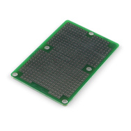
Finally, I have started thinking about how to make a circuit board for this project.  There are basically two options.  First, I could solder all the components and connections on a circuit board like the one to the right.  Or, I could make my own circuit board using the Makerspace's CNC Engraver.  The Engraver may be more work but I would be learning a new skill, a new machine, and possibly have a way to make more of the circuit board quickly.  I might try both methods because I can.

Friday, November 8, 2013

Started Second Tardis

I started 3D printing a second Tardis. Now that I know what I am doing on the 3D printer at the Makerspace, they are coming out much better.  This time, I am printing the sides with 90% infill to make them stronger.  

As you can see from the picture, the blue filament ran out after the first print so I switched to green.  They will all get spray painted navy blue when all the pieces are printed.

I hope to put electrical wiring in this Tardis to make it light up.

By the way, these three pieces took a bit over nine hours to print.